Dell PowerEdge R310 Hardware Owner's Manual - Page 134
Installing the Control Panel Board Assembly and the Control Panel Display Module
 |
View all Dell PowerEdge R310 manuals
Add to My Manuals
Save this manual to your list of manuals |
Page 134 highlights
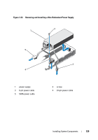
Installing the Control Panel Board Assembly and the Control Panel Display Module For LED control panel, proceed to step 3. Insert the display module into the chassis cutout and secure with the two screws. 1 Affix the replacement panel to the front of the display module. 2 Align the slot in the control panel board with the standoff on the system chassis and secure with the two screws. See Figure 3-24. For LED control panel, skip step 4. 3 Connect the display module cable to the control panel board. 4 Connect the USB and control panel cables to the control panel board. 5 Close the system. See "Closing the System" on page 79. 6 If applicable, replace the optional front bezel. See "Front Bezel (Optional)" on page 77. 7 Reconnect the system to the power source and turn on the system and attached peripherals. 134 Installing System Components
-
 1
1 -
2
-
3
-
4
-
5
-
6
-
7
-
8
-
9
-
10
-
11
-
12
-
13
-
14
-
15
-
16
-
17
-
18
-
19
-
20
-
21
-
22
-
23
-
24
-
25
-
26
-
27
-
28
-
29
-
30
-
31
-
32
-
33
-
34
-
35
-
36
-
37
-
38
-
39
-
40
-
41
-
42
-
43
-
44
-
45
-
46
-
47
-
48
-
49
-
50
-
51
-
52
-
53
-
54
-
55
-
56
-
57
-
58
-
59
-
60
-
61
-
62
-
63
-
64
-
65
-
66
-
67
-
68
-
69
-
70
-
71
-
72
-
73
-
74
-
75
-
76
-
77
-
78
-
79
-
80
-
81
-
82
-
83
-
84
-
85
-
86
-
87
-
88
-
89
-
90
-
91
-
92
-
93
-
94
-
95
-
96
-
97
-
98
-
99
-
100
-
101
-
102
-
103
-
104
-
105
-
106
-
107
-
108
-
109
-
110
-
111
-
112
-
113
-
114
-
115
-
116
-
117
-
118
-
119
-
120
-
121
-
122
-
123
-
124
-
125
-
126
-
127
-
128
-
 129
129 -
 130
130 -
 131
131 -
 132
132 -
 133
133 -
 134
134 -
 135
135 -
 136
136 -
 137
137 -
 138
138 -
 139
139 -
140
-
141
-
142
-
143
-
144
-
145
-
146
-
147
-
148
-
149
-
150
-
151
-
152
-
153
-
154
-
155
-
156
-
157
-
158
-
159
-
160
-
161
-
162
-
163
-
164
-
165
-
166
-
167
-
168
-
169
-
170
-
171
-
172
-
173
-
174
-
175
-
176
 |
 |
