Dell PowerEdge R310 Hardware Owner's Manual - Page 77
Front Bezel (Optional
 |
View all Dell PowerEdge R310 manuals
Add to My Manuals
Save this manual to your list of manuals |
Page 77 highlights
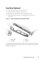
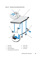
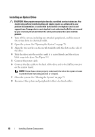
Front Bezel (Optional) 1 Unlock the keylock at the left end of the bezel. 2 Lift up the release latch next to the key lock. 3 Rotate the left end of the bezel away from the front panel. 4 Unhook the right end of the bezel and pull the bezel away from the system. Figure 3-2. Removing and Replacing the Optional Front Bezel 3 2 1 4 1 release latch 3 front bezel 2 keylock 4 hinge tab To replace the optional bezel, hook the right end of the bezel onto the chassis, then fit the free end of the bezel onto the system. Secure the bezel with the keylock. See Figure 3-2. Installing System Components 77
-
 1
1 -
2
-
3
-
4
-
5
-
6
-
7
-
8
-
9
-
10
-
11
-
12
-
13
-
14
-
15
-
16
-
17
-
18
-
19
-
20
-
21
-
22
-
23
-
24
-
25
-
26
-
27
-
28
-
29
-
30
-
31
-
32
-
33
-
34
-
35
-
36
-
37
-
38
-
39
-
40
-
41
-
42
-
43
-
44
-
45
-
46
-
47
-
48
-
49
-
50
-
51
-
52
-
53
-
54
-
55
-
56
-
57
-
58
-
59
-
60
-
61
-
62
-
63
-
64
-
65
-
66
-
67
-
68
-
69
-
70
-
71
-
 72
72 -
 73
73 -
 74
74 -
 75
75 -
 76
76 -
 77
77 -
 78
78 -
 79
79 -
 80
80 -
 81
81 -
 82
82 -
83
-
84
-
85
-
86
-
87
-
88
-
89
-
90
-
91
-
92
-
93
-
94
-
95
-
96
-
97
-
98
-
99
-
100
-
101
-
102
-
103
-
104
-
105
-
106
-
107
-
108
-
109
-
110
-
111
-
112
-
113
-
114
-
115
-
116
-
117
-
118
-
119
-
120
-
121
-
122
-
123
-
124
-
125
-
126
-
127
-
128
-
129
-
130
-
131
-
132
-
133
-
134
-
135
-
136
-
137
-
138
-
139
-
140
-
141
-
142
-
143
-
144
-
145
-
146
-
147
-
148
-
149
-
150
-
151
-
152
-
153
-
154
-
155
-
156
-
157
-
158
-
159
-
160
-
161
-
162
-
163
-
164
-
165
-
166
-
167
-
168
-
169
-
170
-
171
-
172
-
173
-
174
-
175
-
176
 |
 |

Installing System Components
77
Front Bezel (Optional)
1
Unlock the keylock at the left end of the bezel.
2
Lift up the release latch next to the key lock.
3
Rotate the left end of the bezel away from the front panel.
4
Unhook the right end of the bezel and pull the bezel away from
the system.
Figure 3-2.
Removing and Replacing the Optional Front Bezel
To replace the optional bezel, hook the right end of the bezel onto the chassis,
then fit the free end of the bezel onto the system. Secure the bezel with the
keylock. See Figure 3-2.
1
release latch
2
keylock
3
front bezel
4
hinge tab
3
2
1
4