Dell PowerEdge R310 Hardware Owner's Manual - Page 142
Grasp the system board assembly by its edges and lift the assembly away
 |
View all Dell PowerEdge R310 manuals
Add to My Manuals
Save this manual to your list of manuals |
Page 142 highlights
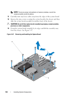
NOTE: To ensure proper reinstallation of memory modules, record the memory module socket locations. 11 Carefully route any loose cables away from the edges of the system board. 12 Remove the nine screws securing the system board to the chassis and then slide the system board assembly toward the front of the chassis. CAUTION: Do not lift the system board assembly by grasping a memory module, processor, or other components. 13 Grasp the system board assembly by its edges and lift the assembly away from the chassis. See Figure 3-27. Figure 3-27. Removing and Installing the System Board 1 2 142 Installing System Components
-
 1
1 -
2
-
3
-
4
-
5
-
6
-
7
-
8
-
9
-
10
-
11
-
12
-
13
-
14
-
15
-
16
-
17
-
18
-
19
-
20
-
21
-
22
-
23
-
24
-
25
-
26
-
27
-
28
-
29
-
30
-
31
-
32
-
33
-
34
-
35
-
36
-
37
-
38
-
39
-
40
-
41
-
42
-
43
-
44
-
45
-
46
-
47
-
48
-
49
-
50
-
51
-
52
-
53
-
54
-
55
-
56
-
57
-
58
-
59
-
60
-
61
-
62
-
63
-
64
-
65
-
66
-
67
-
68
-
69
-
70
-
71
-
72
-
73
-
74
-
75
-
76
-
77
-
78
-
79
-
80
-
81
-
82
-
83
-
84
-
85
-
86
-
87
-
88
-
89
-
90
-
91
-
92
-
93
-
94
-
95
-
96
-
97
-
98
-
99
-
100
-
101
-
102
-
103
-
104
-
105
-
106
-
107
-
108
-
109
-
110
-
111
-
112
-
113
-
114
-
115
-
116
-
117
-
118
-
119
-
120
-
121
-
122
-
123
-
124
-
125
-
126
-
127
-
128
-
129
-
130
-
131
-
132
-
133
-
134
-
135
-
136
-
 137
137 -
 138
138 -
 139
139 -
 140
140 -
 141
141 -
 142
142 -
 143
143 -
 144
144 -
 145
145 -
 146
146 -
 147
147 -
148
-
149
-
150
-
151
-
152
-
153
-
154
-
155
-
156
-
157
-
158
-
159
-
160
-
161
-
162
-
163
-
164
-
165
-
166
-
167
-
168
-
169
-
170
-
171
-
172
-
173
-
174
-
175
-
176
 |
 |

142
Installing System Components
NOTE:
To ensure proper reinstallation of memory modules, record the
memory module socket locations.
11
Carefully route any loose cables away from the edges of the system board.
12
Remove the nine screws securing the system board to the chassis and then
slide the system board assembly toward the front of the chassis.
CAUTION:
Do not lift the system board assembly by grasping a memory module,
processor, or other components.
13
Grasp the system board assembly by its edges and lift the assembly away
from the chassis. See Figure 3-27.
Figure 3-27.
Removing and Installing the System Board
1
1
2