Dell PowerEdge R310 Hardware Owner's Manual - Page 20
Active ID CMA, Power supply 2 PS2 - not turning on
 |
View all Dell PowerEdge R310 manuals
Add to My Manuals
Save this manual to your list of manuals |
Page 20 highlights
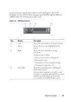
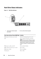
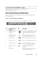
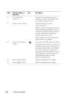
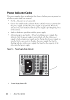
Item Indicator, Button, or Icon Connector 8 Active ID CMA connector 9 System status indicator 10 System identification button 11 Power supply 1 (PS1) 12 Power supply 2 (PS2) Description Connector for attaching a system indicator extension cable that is used on a cable management arm. Lights blue during normal system operation. Both the systems management software and the identification buttons located on the front and back of the system can cause the indicator to flash blue to identify a particular system. Lights amber when the system needs attention due to a problem. Turns the system ID modes on and off. The identification buttons on the front and back panels can be used to locate a particular system within a rack. When one of these buttons is pushed, the LCD panel on the front and the system status indicator on the chassis back panel light blue until one of the buttons is pushed again. 400 W (redundant power supply). 400 W (redundant power supply). 20 About Your System
-
 1
1 -
2
-
3
-
4
-
5
-
6
-
7
-
8
-
9
-
10
-
11
-
12
-
13
-
14
-
 15
15 -
 16
16 -
 17
17 -
 18
18 -
 19
19 -
 20
20 -
 21
21 -
 22
22 -
 23
23 -
 24
24 -
 25
25 -
26
-
27
-
28
-
29
-
30
-
31
-
32
-
33
-
34
-
35
-
36
-
37
-
38
-
39
-
40
-
41
-
42
-
43
-
44
-
45
-
46
-
47
-
48
-
49
-
50
-
51
-
52
-
53
-
54
-
55
-
56
-
57
-
58
-
59
-
60
-
61
-
62
-
63
-
64
-
65
-
66
-
67
-
68
-
69
-
70
-
71
-
72
-
73
-
74
-
75
-
76
-
77
-
78
-
79
-
80
-
81
-
82
-
83
-
84
-
85
-
86
-
87
-
88
-
89
-
90
-
91
-
92
-
93
-
94
-
95
-
96
-
97
-
98
-
99
-
100
-
101
-
102
-
103
-
104
-
105
-
106
-
107
-
108
-
109
-
110
-
111
-
112
-
113
-
114
-
115
-
116
-
117
-
118
-
119
-
120
-
121
-
122
-
123
-
124
-
125
-
126
-
127
-
128
-
129
-
130
-
131
-
132
-
133
-
134
-
135
-
136
-
137
-
138
-
139
-
140
-
141
-
142
-
143
-
144
-
145
-
146
-
147
-
148
-
149
-
150
-
151
-
152
-
153
-
154
-
155
-
156
-
157
-
158
-
159
-
160
-
161
-
162
-
163
-
164
-
165
-
166
-
167
-
168
-
169
-
170
-
171
-
172
-
173
-
174
-
175
-
176
 |
 |
