Dell PowerEdge R920 Dell PowerEdge R920 System Owners Manual - Page 113
Installing The System Board, Removing and Installing the System Board
 |
View all Dell PowerEdge R920 manuals
Add to My Manuals
Save this manual to your list of manuals |
Page 113 highlights
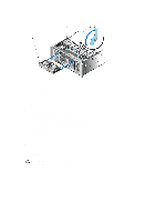
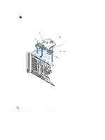
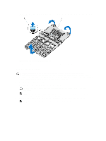
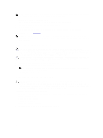
7. Grasp the system-board using the memory riser guides, lift the blue release pin and slide the system board toward the front of the system. Figure 68. Removing and Installing the System Board 1. release pin 2. system board Installing The System Board CAUTION: Many repairs may only be done by a certified service technician. You should only perform troubleshooting and simple repairs as authorized in your product documentation, or as directed by the online or telephone service and support team. Damage due to servicing that is not authorized by Dell is not covered by your warranty. Read and follow the safety instructions that came with the product. 1. Unpack the new system board assembly. 2. Using the memory riser guide, lower the system board into the chassis. CAUTION: Do not lift the system board assembly by grasping a memory module, processor, or other components. NOTE: When installing the system board into the chassis, ensure not to damage the optical drive cable connector that is mounted to the front of the system board. 3. Push the system board toward the back of the chassis until the release pin on the board clicks into place. NOTE: Ensure the two tabs at the back of chassis are placed properly in the slots. 113
-
 1
1 -
2
-
3
-
4
-
5
-
6
-
7
-
8
-
9
-
10
-
11
-
12
-
13
-
14
-
15
-
16
-
17
-
18
-
19
-
20
-
21
-
22
-
23
-
24
-
25
-
26
-
27
-
28
-
29
-
30
-
31
-
32
-
33
-
34
-
35
-
36
-
37
-
38
-
39
-
40
-
41
-
42
-
43
-
44
-
45
-
46
-
47
-
48
-
49
-
50
-
51
-
52
-
53
-
54
-
55
-
56
-
57
-
58
-
59
-
60
-
61
-
62
-
63
-
64
-
65
-
66
-
67
-
68
-
69
-
70
-
71
-
72
-
73
-
74
-
75
-
76
-
77
-
78
-
79
-
80
-
81
-
82
-
83
-
84
-
85
-
86
-
87
-
88
-
89
-
90
-
91
-
92
-
93
-
94
-
95
-
96
-
97
-
98
-
99
-
100
-
101
-
102
-
103
-
104
-
105
-
106
-
107
-
 108
108 -
 109
109 -
 110
110 -
 111
111 -
 112
112 -
 113
113 -
 114
114 -
 115
115 -
 116
116 -
 117
117 -
 118
118 -
119
-
120
-
121
-
122
-
123
-
124
-
125
-
126
-
127
-
128
-
129
-
130
-
131
-
132
-
133
-
134
-
135
-
136
-
137
-
138
-
139
-
140
-
141
-
142
-
143
-
144
-
145
-
146
-
147
-
148
-
149
-
150
-
151
-
152
-
153
-
154
-
155
-
156
-
157
-
158
 |
 |
