Dell PowerEdge R920 Dell PowerEdge R920 System Owners Manual - Page 94
Installing A DC Power Supply, Removing and Installing a DC Power Supply
 |
View all Dell PowerEdge R920 manuals
Add to My Manuals
Save this manual to your list of manuals |
Page 94 highlights
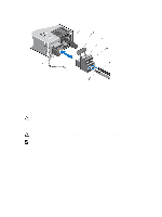
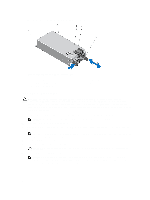
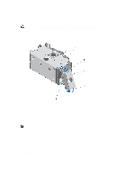
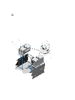
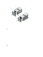
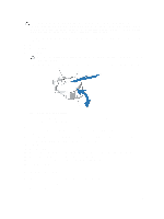
3. Press the release latch and slide the power supply out of the chassis. Figure 49. Removing and Installing a DC Power Supply 1. connector 3. power supply status indicator 5. power supply handle 2. power supply 4. release latch Installing A DC Power Supply WARNING: For equipment using -(48-60) V DC power supplies, a qualified electrician must perform all connections to DC power and to safety grounds. Do not attempt connecting to DC power or installing grounds yourself. All electrical wiring must comply with applicable local or national codes and practices. Damage due to servicing that is not authorized by Dell is not covered by your warranty. Read and follow all safety instructions that came with the product. 1. Verify that both the power supplies are the same type and have the same maximum output power. NOTE: The maximum output power (shown in Watts) is listed on the power supply label. 2. If applicable, remove the power supply blank. 3. Slide the new power supply into the chassis until the power supply is fully seated and the release latch snaps into place. NOTE: If you unlatched the cable management arm, re-latch it. For information about the cable management arm, see the system's rack documentation. 4. Connect the safety ground wire. 5. Install the DC power connector in the power supply. CAUTION: When connecting the power wires, secure the wires with the strap to the power supply handle. 6. Connect the wires to a DC power source. NOTE: When installing, hot-swapping, or hot-adding a new power supply, allow several seconds for the system to recognize the power supply and determine its status. The power-supply status indicator turns green to signify that the power supply is functioning properly. 94
-
 1
1 -
2
-
3
-
4
-
5
-
6
-
7
-
8
-
9
-
10
-
11
-
12
-
13
-
14
-
15
-
16
-
17
-
18
-
19
-
20
-
21
-
22
-
23
-
24
-
25
-
26
-
27
-
28
-
29
-
30
-
31
-
32
-
33
-
34
-
35
-
36
-
37
-
38
-
39
-
40
-
41
-
42
-
43
-
44
-
45
-
46
-
47
-
48
-
49
-
50
-
51
-
52
-
53
-
54
-
55
-
56
-
57
-
58
-
59
-
60
-
61
-
62
-
63
-
64
-
65
-
66
-
67
-
68
-
69
-
70
-
71
-
72
-
73
-
74
-
75
-
76
-
77
-
78
-
79
-
80
-
81
-
82
-
83
-
84
-
85
-
86
-
87
-
88
-
 89
89 -
 90
90 -
 91
91 -
 92
92 -
 93
93 -
 94
94 -
 95
95 -
 96
96 -
 97
97 -
 98
98 -
 99
99 -
100
-
101
-
102
-
103
-
104
-
105
-
106
-
107
-
108
-
109
-
110
-
111
-
112
-
113
-
114
-
115
-
116
-
117
-
118
-
119
-
120
-
121
-
122
-
123
-
124
-
125
-
126
-
127
-
128
-
129
-
130
-
131
-
132
-
133
-
134
-
135
-
136
-
137
-
138
-
139
-
140
-
141
-
142
-
143
-
144
-
145
-
146
-
147
-
148
-
149
-
150
-
151
-
152
-
153
-
154
-
155
-
156
-
157
-
158
 |
 |
