Dell PowerEdge R920 Dell PowerEdge R920 System Owners Manual - Page 53
Memory Riser And Fan Cage, Removing The Memory Riser And Fan Cage
 |
View all Dell PowerEdge R920 manuals
Add to My Manuals
Save this manual to your list of manuals |
Page 53 highlights
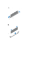
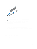
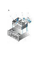
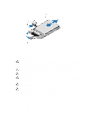
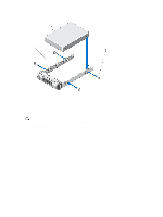
8. Press down on the memory module with your thumbs until the memory module snaps into place. Figure 20. Installing The Memory Module 1. memory module 3. memory-module socket alignment key 2. memory-module ejectors 4. memory-module alignment key NOTE: When the memory module is properly seated in the socket, the levers on the memory-module socket align with the levers on the other identical sockets that have memory modules installed. 9. Repeat step 5 through step 8 of this procedure to install the remaining memory modules. 10. Close the memory riser cover. 11. Install the memory riser. 12. Close the system. 13. Reconnect the system to its electrical outlet and turn on the system, including any attached peripherals. 14. Press to enter the System Setup, and check the memory settings. The system should have already changed the value to reflect the newly installed memory. 15. If the value is incorrect, one or more of the memory modules may not be installed properly. Repeat step 5 through step 8 of this procedure, checking to ensure that the memory modules are firmly seated in their sockets. 16. Run the appropriate diagnostic test. For more information, see Using System Diagnostics. Memory Riser And Fan Cage Memory riser cage and fan cage (single unit) is located inside the system between the hard-drive backplane and the cable management tray, that is above the processor heat sinks. Removing The Memory Riser And Fan Cage 1. Turn off the system, including any attached peripherals, and disconnect the system from the electrical outlet. 2. Open the system. 3. If applicable, remove the memory-riser blanks. 4. Remove memory risers. 5. Remove cooling fans. 6. Remove the memory riser and fan cage. 7. Remove the cable management tray. 53
-
 1
1 -
2
-
3
-
4
-
5
-
6
-
7
-
8
-
9
-
10
-
11
-
12
-
13
-
14
-
15
-
16
-
17
-
18
-
19
-
20
-
21
-
22
-
23
-
24
-
25
-
26
-
27
-
28
-
29
-
30
-
31
-
32
-
33
-
34
-
35
-
36
-
37
-
38
-
39
-
40
-
41
-
42
-
43
-
44
-
45
-
46
-
47
-
 48
48 -
 49
49 -
 50
50 -
 51
51 -
 52
52 -
 53
53 -
 54
54 -
 55
55 -
 56
56 -
 57
57 -
 58
58 -
59
-
60
-
61
-
62
-
63
-
64
-
65
-
66
-
67
-
68
-
69
-
70
-
71
-
72
-
73
-
74
-
75
-
76
-
77
-
78
-
79
-
80
-
81
-
82
-
83
-
84
-
85
-
86
-
87
-
88
-
89
-
90
-
91
-
92
-
93
-
94
-
95
-
96
-
97
-
98
-
99
-
100
-
101
-
102
-
103
-
104
-
105
-
106
-
107
-
108
-
109
-
110
-
111
-
112
-
113
-
114
-
115
-
116
-
117
-
118
-
119
-
120
-
121
-
122
-
123
-
124
-
125
-
126
-
127
-
128
-
129
-
130
-
131
-
132
-
133
-
134
-
135
-
136
-
137
-
138
-
139
-
140
-
141
-
142
-
143
-
144
-
145
-
146
-
147
-
148
-
149
-
150
-
151
-
152
-
153
-
154
-
155
-
156
-
157
-
158
 |
 |
