Dell PowerEdge R920 Dell PowerEdge R920 System Owners Manual - Page 62
Installing The Fan tray, Internal USB Memory Key (Optional)
 |
View all Dell PowerEdge R920 manuals
Add to My Manuals
Save this manual to your list of manuals |
Page 62 highlights
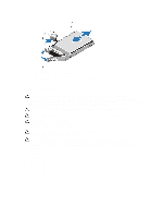
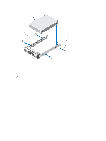
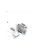
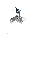
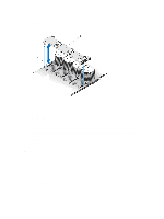
8. Disengage the fan tray from the connector on the system board. 9. Lift and remove the fan tray out of the system chassis. Figure 27. Removing and Installing the Fan Tray 1. fan tray connector 2. fan tray Installing The Fan tray 1. Align the fan tray with the connector and the screw holes on the system board. 2. Lower the fan tray and ensure that the fan tray connector engages with the connector on the system board. 3. Using a #2 Phillips screwdriver, tighten the fan tray screws (2 screws on the left and 1 screw on the right side) to the system board. 4. Install the memory riser and fan cage. 5. Install the cooling fans. 6. Install the memory risers. 7. Close the system. 8. Reconnect the system to its electrical outlet and turn the system on, including any attached peripherals. Internal USB Memory Key (Optional) An optional USB memory key installed on your system can be used as a boot device, security key, or mass storage device. The USB connector must be enabled by the Internal USB Port option in the Integrated Devices screen of the System Setup. To boot from the USB memory key, configure the USB memory key with a boot image and then specify the USB memory key in the boot sequence in the System Setup. 62
-
 1
1 -
2
-
3
-
4
-
5
-
6
-
7
-
8
-
9
-
10
-
11
-
12
-
13
-
14
-
15
-
16
-
17
-
18
-
19
-
20
-
21
-
22
-
23
-
24
-
25
-
26
-
27
-
28
-
29
-
30
-
31
-
32
-
33
-
34
-
35
-
36
-
37
-
38
-
39
-
40
-
41
-
42
-
43
-
44
-
45
-
46
-
47
-
48
-
49
-
50
-
51
-
52
-
53
-
54
-
55
-
56
-
 57
57 -
 58
58 -
 59
59 -
 60
60 -
 61
61 -
 62
62 -
 63
63 -
 64
64 -
 65
65 -
 66
66 -
 67
67 -
68
-
69
-
70
-
71
-
72
-
73
-
74
-
75
-
76
-
77
-
78
-
79
-
80
-
81
-
82
-
83
-
84
-
85
-
86
-
87
-
88
-
89
-
90
-
91
-
92
-
93
-
94
-
95
-
96
-
97
-
98
-
99
-
100
-
101
-
102
-
103
-
104
-
105
-
106
-
107
-
108
-
109
-
110
-
111
-
112
-
113
-
114
-
115
-
116
-
117
-
118
-
119
-
120
-
121
-
122
-
123
-
124
-
125
-
126
-
127
-
128
-
129
-
130
-
131
-
132
-
133
-
134
-
135
-
136
-
137
-
138
-
139
-
140
-
141
-
142
-
143
-
144
-
145
-
146
-
147
-
148
-
149
-
150
-
151
-
152
-
153
-
154
-
155
-
156
-
157
-
158
 |
 |
