Dell PowerEdge R920 Dell PowerEdge R920 System Owners Manual - Page 96
Removing The Power Supply Bay, Removing and Installing the Power Supply Bay
 |
View all Dell PowerEdge R920 manuals
Add to My Manuals
Save this manual to your list of manuals |
Page 96 highlights
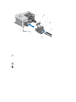
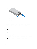
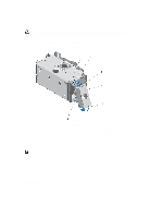
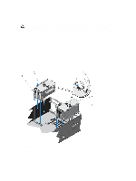
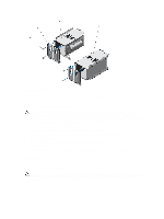
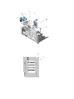
Removing The Power Supply Bay CAUTION: Many repairs may only be done by a certified service technician. You should only perform troubleshooting and simple repairs as authorized in your product documentation, or as directed by the online or telephone service and support team. Damage due to servicing that is not authorized by Dell is not covered by your warranty. Read and follow the safety instructions that came with the product. 1. Turn off the system, including any attached peripherals, and disconnect the system from the electrical outlet. 2. Open the system. 3. As applicable, remove the AC or DC power supply and power supply blanks from the power supply bay. 4. Remove the storage controller card (applicable for the left power supply bay). 5. If applicable, remove the optional riser 2 and 3. 6. Press the spring latch (with your index finger and thumb) on top of the power supply bay and pull the bay away from the chassis side wall. 7. Pull the power supply bay, so that the PDB is disconnected from the connector on the system board. Follow the same procedure for the removal of other power supply bay in the system. Figure 51. Removing and Installing the Power Supply Bay 1. PDB connector on the system board 3. power supply bay (left) 2. PDB 4. power supply bay (right) 96
-
 1
1 -
2
-
3
-
4
-
5
-
6
-
7
-
8
-
9
-
10
-
11
-
12
-
13
-
14
-
15
-
16
-
17
-
18
-
19
-
20
-
21
-
22
-
23
-
24
-
25
-
26
-
27
-
28
-
29
-
30
-
31
-
32
-
33
-
34
-
35
-
36
-
37
-
38
-
39
-
40
-
41
-
42
-
43
-
44
-
45
-
46
-
47
-
48
-
49
-
50
-
51
-
52
-
53
-
54
-
55
-
56
-
57
-
58
-
59
-
60
-
61
-
62
-
63
-
64
-
65
-
66
-
67
-
68
-
69
-
70
-
71
-
72
-
73
-
74
-
75
-
76
-
77
-
78
-
79
-
80
-
81
-
82
-
83
-
84
-
85
-
86
-
87
-
88
-
89
-
90
-
 91
91 -
 92
92 -
 93
93 -
 94
94 -
 95
95 -
 96
96 -
 97
97 -
 98
98 -
 99
99 -
 100
100 -
 101
101 -
102
-
103
-
104
-
105
-
106
-
107
-
108
-
109
-
110
-
111
-
112
-
113
-
114
-
115
-
116
-
117
-
118
-
119
-
120
-
121
-
122
-
123
-
124
-
125
-
126
-
127
-
128
-
129
-
130
-
131
-
132
-
133
-
134
-
135
-
136
-
137
-
138
-
139
-
140
-
141
-
142
-
143
-
144
-
145
-
146
-
147
-
148
-
149
-
150
-
151
-
152
-
153
-
154
-
155
-
156
-
157
-
158
 |
 |
