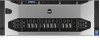
Dell PowerEdge R920 Dell PowerEdge R920 System Owners Manual - Page 14
Back-Panel Features And Indicators, W, 1100 W, or 1600 W when
 |
View all Dell PowerEdge R920 manuals
Add to My Manuals
Save this manual to your list of manuals |
Page 14 highlights
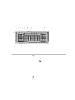
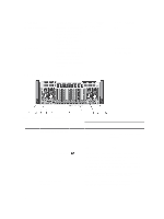
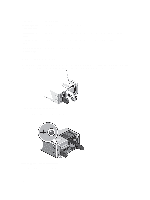
State Name Device identify (blink) Device failed Slot/Device State Status LED (Green) The device is identifying the slot location or is indicating the device has received a Prepare for Removal command from the host operating system. On for 250 msec Off for 250 msec The host operating system Off no longer has access to the device because the device is not responding or has encountered a critical error condition. Back-Panel Features And Indicators Status LED (Amber) Off On for 250 msec Off for 250 msec Figure 5. Back-Panel Features and Indicators Item Indicator, Button, or Icon Connector 1 Power supply (PSU 3 and 4) 2 System identification button 3 System identification connector Description AC 750 W, 1100 W, or 1600 W (when available) or DC 1100 W The identification buttons on the front and back panels can be used to locate a particular system within a rack. Press to toggle the system ID on and off. If the system stops responding during POST, press and hold the system ID button for more than five seconds to enter BIOS progress mode. To reset iDRAC (if not disabled in F2 iDRAC setup) press and hold the button for more than 15 seconds. Connects the optional system status indicator assembly through the optional cable management arm. 14
-
 1
1 -
2
-
3
-
4
-
5
-
6
-
7
-
8
-
 9
9 -
 10
10 -
 11
11 -
 12
12 -
 13
13 -
 14
14 -
 15
15 -
 16
16 -
 17
17 -
 18
18 -
 19
19 -
20
-
21
-
22
-
23
-
24
-
25
-
26
-
27
-
28
-
29
-
30
-
31
-
32
-
33
-
34
-
35
-
36
-
37
-
38
-
39
-
40
-
41
-
42
-
43
-
44
-
45
-
46
-
47
-
48
-
49
-
50
-
51
-
52
-
53
-
54
-
55
-
56
-
57
-
58
-
59
-
60
-
61
-
62
-
63
-
64
-
65
-
66
-
67
-
68
-
69
-
70
-
71
-
72
-
73
-
74
-
75
-
76
-
77
-
78
-
79
-
80
-
81
-
82
-
83
-
84
-
85
-
86
-
87
-
88
-
89
-
90
-
91
-
92
-
93
-
94
-
95
-
96
-
97
-
98
-
99
-
100
-
101
-
102
-
103
-
104
-
105
-
106
-
107
-
108
-
109
-
110
-
111
-
112
-
113
-
114
-
115
-
116
-
117
-
118
-
119
-
120
-
121
-
122
-
123
-
124
-
125
-
126
-
127
-
128
-
129
-
130
-
131
-
132
-
133
-
134
-
135
-
136
-
137
-
138
-
139
-
140
-
141
-
142
-
143
-
144
-
145
-
146
-
147
-
148
-
149
-
150
-
151
-
152
-
153
-
154
-
155
-
156
-
157
-
158
 |
 |
