Dell PowerEdge R920 Dell PowerEdge R920 System Owners Manual - Page 87
Installing A Processor, Removing and Installing a Processor
 |
View all Dell PowerEdge R920 manuals
Add to My Manuals
Save this manual to your list of manuals |
Page 87 highlights
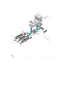
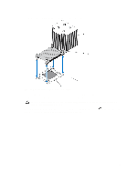
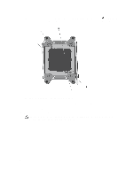
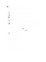
15. Lift the processor out of the socket and leave the release lever up so that the socket is ready for the new processor. Figure 45. Removing and Installing a Processor 1. processor socket-release lever 3. processor shield 5. notches in processor 7. pin 1 indicator 2. processor 4. processor socket-release lever 6. socket keys 8. ZIF socket NOTE: After removing the processor, place it in an antistatic container for reuse, return, or temporary storage. Do not touch the bottom of the processor. Touch only the side edges of the processor. NOTE: If you are permanently removing the processor, you must install a socket protective cap in the vacant socket to protect the socket pins and keep the socket free of dust. Installing A Processor CAUTION: Many repairs may only be done by a certified service technician. You should only perform troubleshooting and simple repairs as authorized in your product documentation, or as directed by the online or telephone service and support team. Damage due to servicing that is not authorized by Dell is not covered by your warranty. Read and follow the safety instructions that came with the product. 87
-
 1
1 -
2
-
3
-
4
-
5
-
6
-
7
-
8
-
9
-
10
-
11
-
12
-
13
-
14
-
15
-
16
-
17
-
18
-
19
-
20
-
21
-
22
-
23
-
24
-
25
-
26
-
27
-
28
-
29
-
30
-
31
-
32
-
33
-
34
-
35
-
36
-
37
-
38
-
39
-
40
-
41
-
42
-
43
-
44
-
45
-
46
-
47
-
48
-
49
-
50
-
51
-
52
-
53
-
54
-
55
-
56
-
57
-
58
-
59
-
60
-
61
-
62
-
63
-
64
-
65
-
66
-
67
-
68
-
69
-
70
-
71
-
72
-
73
-
74
-
75
-
76
-
77
-
78
-
79
-
80
-
81
-
 82
82 -
 83
83 -
 84
84 -
 85
85 -
 86
86 -
 87
87 -
 88
88 -
 89
89 -
 90
90 -
 91
91 -
 92
92 -
93
-
94
-
95
-
96
-
97
-
98
-
99
-
100
-
101
-
102
-
103
-
104
-
105
-
106
-
107
-
108
-
109
-
110
-
111
-
112
-
113
-
114
-
115
-
116
-
117
-
118
-
119
-
120
-
121
-
122
-
123
-
124
-
125
-
126
-
127
-
128
-
129
-
130
-
131
-
132
-
133
-
134
-
135
-
136
-
137
-
138
-
139
-
140
-
141
-
142
-
143
-
144
-
145
-
146
-
147
-
148
-
149
-
150
-
151
-
152
-
153
-
154
-
155
-
156
-
157
-
158
 |
 |
