Dell PowerEdge R920 Dell PowerEdge R920 System Owners Manual - Page 54
Removing and Installing the Memory Riser and Fan Cage
 |
View all Dell PowerEdge R920 manuals
Add to My Manuals
Save this manual to your list of manuals |
Page 54 highlights
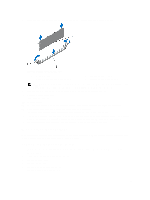
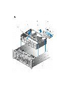
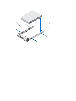
8. Remove the backplane cables connected to the system board through the cage. 9. Locate the handle lock on the cage and slide the lock in the direction of the arrow. 10. Lift the cage holding the cage-handle and the back of the cage. Pull the memory riser and fan cage out of the system chassis. NOTE: As the cage handle is located off-center, use the back of the cage to remove the memory riser and fan cage. Figure 21. Removing and Installing the Memory Riser and Fan Cage 1. memory riser and fan cage handle 2. 3. memory riser and fan cage back handle 4. 5. cage guides on the side of the chassis fan cage handle lock 54
-
 1
1 -
2
-
3
-
4
-
5
-
6
-
7
-
8
-
9
-
10
-
11
-
12
-
13
-
14
-
15
-
16
-
17
-
18
-
19
-
20
-
21
-
22
-
23
-
24
-
25
-
26
-
27
-
28
-
29
-
30
-
31
-
32
-
33
-
34
-
35
-
36
-
37
-
38
-
39
-
40
-
41
-
42
-
43
-
44
-
45
-
46
-
47
-
48
-
 49
49 -
 50
50 -
 51
51 -
 52
52 -
 53
53 -
 54
54 -
 55
55 -
 56
56 -
 57
57 -
 58
58 -
 59
59 -
60
-
61
-
62
-
63
-
64
-
65
-
66
-
67
-
68
-
69
-
70
-
71
-
72
-
73
-
74
-
75
-
76
-
77
-
78
-
79
-
80
-
81
-
82
-
83
-
84
-
85
-
86
-
87
-
88
-
89
-
90
-
91
-
92
-
93
-
94
-
95
-
96
-
97
-
98
-
99
-
100
-
101
-
102
-
103
-
104
-
105
-
106
-
107
-
108
-
109
-
110
-
111
-
112
-
113
-
114
-
115
-
116
-
117
-
118
-
119
-
120
-
121
-
122
-
123
-
124
-
125
-
126
-
127
-
128
-
129
-
130
-
131
-
132
-
133
-
134
-
135
-
136
-
137
-
138
-
139
-
140
-
141
-
142
-
143
-
144
-
145
-
146
-
147
-
148
-
149
-
150
-
151
-
152
-
153
-
154
-
155
-
156
-
157
-
158
 |
 |

8.
Remove the backplane cables connected to the system board through the cage.
9.
Locate the handle lock on the cage and slide the lock in the direction of the arrow.
10.
Lift the cage holding the cage-handle and the back of the cage. Pull the memory riser and fan cage out of the
system chassis.
NOTE:
As the cage handle is located off-center, use the back of the cage to remove the memory riser and fan
cage.
Figure 21. Removing and Installing the Memory Riser and Fan Cage
1.
memory riser and fan cage handle
2.
fan cage
3.
memory riser and fan cage back handle
4.
handle lock
5.
cage guides on the side of the chassis
54