Dell PowerVault 56F Dell PowerVault 56F 16-Port Fibre Channel Switch Inst - Page 46
VC Link Ctl, VC Class 2, VC Class 3, VC Multicast, VC Muticast
 |
View all Dell PowerVault 56F manuals
Add to My Manuals
Save this manual to your list of manuals |
Page 46 highlights
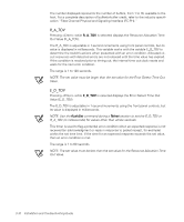
Pressing while VC Link Ctl is selected displays the virtual channel link control channel. The Virtual Channel Link Control changes the link control channel. There are two options: 0 and 1. Option 0 forces data receipt acknowledgments on Class 2 channels to be sent back on the data channel. This traffic consumes a portion of the available data channel bandwidth. Option 1 allows data receipt acknowledgment packets to use the VD-1 (internal switch traffic channel) which frees additional bandwidth in the data channel, and transfers the data receipt traffic load to the switch's internal traffic channel. Pressing while VC Class 2 is selected displays the virtual channel 2 setting. You can select the default channel of 2, but you can also select virtual channel 3, 4, or 5. Pressing while VC Class 3 is selected displays the virtual channel 3 setting. You can select the default channel as 3, but you can select virtual channel 2, 4, or 5. Pressing while VC Multicast is selected displays the virtual channel multicast channel. You may change the multicast transmission channel to either virtual channel 6 or 7. Verify that the multicast channel has the frame class priority set to the frame class of the expected traffic. Pressing while VC Muticast is selected displays the priorities assigned to each of the switch's virtual channels. Positions 1 and 2, starting at the left of the display, are fixed and display 0 or 1. The first position, a 0 ,shows and indicates that this virtual channel, assigned to handle internal switch traffic, has the highest priority. This priority value cannot be changed by the user. The second position, indicated by a 1, shows the priority assigned by the virtual channel link control as described in the "VC Link Ctl" section. The third through eighth positions can have only a 2 or a 3 indicating that the channel gives priority to either Class 2 frame traffic or to Class 3 frame traffic. 3-12 Installation and Troubleshooting Guide
-
 1
1 -
2
-
3
-
4
-
5
-
6
-
7
-
8
-
9
-
10
-
11
-
12
-
13
-
14
-
15
-
16
-
17
-
18
-
19
-
20
-
21
-
22
-
23
-
24
-
25
-
26
-
27
-
28
-
29
-
30
-
31
-
32
-
33
-
34
-
35
-
36
-
37
-
38
-
39
-
40
-
 41
41 -
 42
42 -
 43
43 -
 44
44 -
 45
45 -
 46
46 -
 47
47 -
 48
48 -
 49
49 -
 50
50 -
 51
51 -
52
-
53
-
54
-
55
-
56
-
57
-
58
-
59
-
60
-
61
-
62
-
63
-
64
-
65
-
66
-
67
-
68
-
69
-
70
-
71
-
72
-
73
-
74
-
75
-
76
-
77
-
78
-
79
-
80
-
81
-
82
-
83
-
84
-
85
-
86
-
87
-
88
-
89
-
90
-
91
-
92
-
93
-
94
-
95
-
96
-
97
-
98
-
99
-
100
-
101
-
102
-
103
-
104
-
105
-
106
-
107
-
108
-
109
-
110
-
111
-
112
-
113
-
114
-
115
-
116
-
117
-
118
-
119
-
120
-
121
-
122
-
123
-
124
-
125
-
126
-
127
-
128
-
129
-
130
-
131
-
132
-
133
-
134
-
135
-
136
-
137
-
138
-
139
-
140
-
141
-
142
-
143
-
144
-
145
-
146
-
147
-
148
-
149
-
150
-
151
-
152
-
153
-
154
-
155
-
156
-
157
-
158
-
159
-
160
-
161
-
162
-
163
-
164
-
165
-
166
-
167
-
168
-
169
-
170
-
171
-
172
 |
 |
