Epson C3400 Technical Reference Guide TRG - Page 16
Power Switch, Power Switch Cover, CAUTION, WARNING
 |
View all Epson C3400 manuals
Add to My Manuals
Save this manual to your list of manuals |
Page 16 highlights
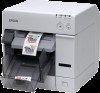
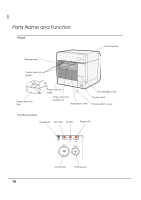
Power Switch CAUTION Before turning on the printer, be sure to check that the AC adapter is connected to the power supply. • When DIP switch 1 is OFF, the power is turned on after the POWER button has been pressed while the power is OFF. • When DIP switch 1 is OFF, the power is turned off after the POWER button has been pressed for approximately 3 seconds while the power is ON. • When DIP switch 1 is ON, the printer settings are reset after the POWER button has been pressed for approximately 3 seconds. See "Setting the DIP Switches" on page 77 for DIP switch setting. Power Switch Cover Attaching the power switch cover prevents accidental pressing of the power switch. ∗ To prevent the power switch from being pressed: Attach the power switch cover as it is (without punching a hole in it). ∗ To prevent the power switch from being pressed unless a long, thin object is pressed into a hole in the power switch cover: Attach the power switch cover after punching a hole in it. For details about attaching the power switch cover, see "Attaching the Power Switch Cover" on page 101. Be sure to change the DIP switch setting when you want to attach the power switch cover without punching a hole in it. (See "Setting the DIP Switches" on page 77.) WARNING Make sure to pull out the AC cable if the printer is damaged when attaching the power switch cover. Using it as it is may cause a fire. 16
-
 1
1 -
2
-
3
-
4
-
5
-
6
-
7
-
8
-
9
-
10
-
 11
11 -
 12
12 -
 13
13 -
 14
14 -
 15
15 -
 16
16 -
 17
17 -
 18
18 -
 19
19 -
 20
20 -
 21
21 -
22
-
23
-
24
-
25
-
26
-
27
-
28
-
29
-
30
-
31
-
32
-
33
-
34
-
35
-
36
-
37
-
38
-
39
-
40
-
41
-
42
-
43
-
44
-
45
-
46
-
47
-
48
-
49
-
50
-
51
-
52
-
53
-
54
-
55
-
56
-
57
-
58
-
59
-
60
-
61
-
62
-
63
-
64
-
65
-
66
-
67
-
68
-
69
-
70
-
71
-
72
-
73
-
74
-
75
-
76
-
77
-
78
-
79
-
80
-
81
-
82
-
83
-
84
-
85
-
86
-
87
-
88
-
89
-
90
-
91
-
92
-
93
-
94
-
95
-
96
-
97
-
98
-
99
-
100
-
101
-
102
-
103
-
104
-
105
-
106
-
107
-
108
-
109
-
110
-
111
-
112
-
113
-
114
-
115
-
116
-
117
-
118
-
119
-
120
-
121
-
122
-
123
-
124
-
125
-
126
-
127
-
128
-
129
-
130
-
131
-
132
-
133
-
134
-
135
-
136
-
137
-
138
-
139
-
140
-
141
-
142
-
143
-
144
-
145
-
146
-
147
-
148
-
149
-
150
-
151
-
152
-
153
-
154
-
155
-
156
-
157
-
158
-
159
-
160
-
161
-
162
-
163
-
164
-
165
-
166
-
167
-
168
-
169
-
170
-
171
-
172
-
173
-
174
-
175
-
176
-
177
-
178
-
179
-
180
-
181
-
182
-
183
-
184
-
185
-
186
-
187
-
188
-
189
-
190
-
191
-
192
-
193
-
194
-
195
-
196
-
197
-
198
-
199
-
200
-
201
-
202
-
203
-
204
-
205
-
206
-
207
-
208
-
209
-
210
-
211
-
212
-
213
-
214
-
215
-
216
-
217
-
218
-
219
-
220
-
221
-
222
-
223
-
224
-
225
-
226
-
227
-
228
-
229
-
230
-
231
-
232
-
233
-
234
-
235
-
236
-
237
-
238
-
239
-
240
-
241
-
242
 |
 |
