Epson C3400 Technical Reference Guide TRG - Page 240
Ethernet interface model, he USB ser
 |
View all Epson C3400 manuals
Add to My Manuals
Save this manual to your list of manuals |
Page 240 highlights
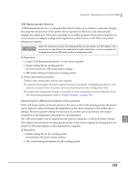
❏ Procedure for replacing the printer ➀ Connect the new printer to the administrator computer and turn on the printer. ➁ Configure the existing printer settings in the printer. The USB serial number in the printer setting file for the existing printer will be the USB serial number of the new printer. Set the printer's DIP switches to match the DIP switch setting information of the existing printer. (Refer to "Setup Procedure" on page 225.) ➂ Remove the existing printer from the client computer. ➃ Connect the new printer to the client computer and turn on the printer. Ethernet interface model Configure the IP address and other network settings of the existing printer and the settings of the existing printer in the new printer. There is no need to configure the printer driver on the client computer. ❏ Preparation • The network setting information of the existing printer (IP address and so on) Print the status sheet with the existing printer. (See "Status Sheet Printing (Ethernet interface model only)" on page 200.) • The printer setting file of the existing printer • Confirm the DIP switch setting for the existing printer. ❏ Replacing procedure ➀ Set the new printer's DIP switch settings to the same as that of the existing printer. ➁ Connect the new printer to the network, and turn it on. ➂ Make the network setting for the new printer according to the printed status sheet using EpsonNet Config. ➃ Make the setting to the new printer using the printer setting file with the Printer Setting. 240
-
 1
1 -
2
-
3
-
4
-
5
-
6
-
7
-
8
-
9
-
10
-
11
-
12
-
13
-
14
-
15
-
16
-
17
-
18
-
19
-
20
-
21
-
22
-
23
-
24
-
25
-
26
-
27
-
28
-
29
-
30
-
31
-
32
-
33
-
34
-
35
-
36
-
37
-
38
-
39
-
40
-
41
-
42
-
43
-
44
-
45
-
46
-
47
-
48
-
49
-
50
-
51
-
52
-
53
-
54
-
55
-
56
-
57
-
58
-
59
-
60
-
61
-
62
-
63
-
64
-
65
-
66
-
67
-
68
-
69
-
70
-
71
-
72
-
73
-
74
-
75
-
76
-
77
-
78
-
79
-
80
-
81
-
82
-
83
-
84
-
85
-
86
-
87
-
88
-
89
-
90
-
91
-
92
-
93
-
94
-
95
-
96
-
97
-
98
-
99
-
100
-
101
-
102
-
103
-
104
-
105
-
106
-
107
-
108
-
109
-
110
-
111
-
112
-
113
-
114
-
115
-
116
-
117
-
118
-
119
-
120
-
121
-
122
-
123
-
124
-
125
-
126
-
127
-
128
-
129
-
130
-
131
-
132
-
133
-
134
-
135
-
136
-
137
-
138
-
139
-
140
-
141
-
142
-
143
-
144
-
145
-
146
-
147
-
148
-
149
-
150
-
151
-
152
-
153
-
154
-
155
-
156
-
157
-
158
-
159
-
160
-
161
-
162
-
163
-
164
-
165
-
166
-
167
-
168
-
169
-
170
-
171
-
172
-
173
-
174
-
175
-
176
-
177
-
178
-
179
-
180
-
181
-
182
-
183
-
184
-
185
-
186
-
187
-
188
-
189
-
190
-
191
-
192
-
193
-
194
-
195
-
196
-
197
-
198
-
199
-
200
-
201
-
202
-
203
-
204
-
205
-
206
-
207
-
208
-
209
-
210
-
211
-
212
-
213
-
214
-
215
-
216
-
217
-
218
-
219
-
220
-
221
-
222
-
223
-
224
-
225
-
226
-
227
-
228
-
229
-
230
-
231
-
232
-
233
-
234
-
 235
235 -
 236
236 -
 237
237 -
 238
238 -
 239
239 -
 240
240 -
 241
241 -
 242
242
 |
 |
