Epson C3400 Technical Reference Guide TRG - Page 204
Changing the Interface for Ethernet Model
 |
View all Epson C3400 manuals
Add to My Manuals
Save this manual to your list of manuals |
Page 204 highlights
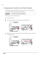
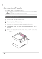
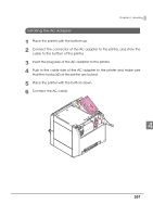
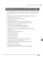
Changing the Interface for Ethernet Model For the Ethernet interface model, the Ethernet interface can be changed to the USB interface. For the USB interface model, the interface cannot be changed. • Keep the removed parts so that they will not be lost. • Use the USB cable included in the product package. Follow the steps below to change the interface. 1 Turn off the printer. 2 Open the connector cover, and remove the LAN cable. 3 Remove the 2 screws indicated by the red circles below to remove the connector cover. 204
-
 1
1 -
2
-
3
-
4
-
5
-
6
-
7
-
8
-
9
-
10
-
11
-
12
-
13
-
14
-
15
-
16
-
17
-
18
-
19
-
20
-
21
-
22
-
23
-
24
-
25
-
26
-
27
-
28
-
29
-
30
-
31
-
32
-
33
-
34
-
35
-
36
-
37
-
38
-
39
-
40
-
41
-
42
-
43
-
44
-
45
-
46
-
47
-
48
-
49
-
50
-
51
-
52
-
53
-
54
-
55
-
56
-
57
-
58
-
59
-
60
-
61
-
62
-
63
-
64
-
65
-
66
-
67
-
68
-
69
-
70
-
71
-
72
-
73
-
74
-
75
-
76
-
77
-
78
-
79
-
80
-
81
-
82
-
83
-
84
-
85
-
86
-
87
-
88
-
89
-
90
-
91
-
92
-
93
-
94
-
95
-
96
-
97
-
98
-
99
-
100
-
101
-
102
-
103
-
104
-
105
-
106
-
107
-
108
-
109
-
110
-
111
-
112
-
113
-
114
-
115
-
116
-
117
-
118
-
119
-
120
-
121
-
122
-
123
-
124
-
125
-
126
-
127
-
128
-
129
-
130
-
131
-
132
-
133
-
134
-
135
-
136
-
137
-
138
-
139
-
140
-
141
-
142
-
143
-
144
-
145
-
146
-
147
-
148
-
149
-
150
-
151
-
152
-
153
-
154
-
155
-
156
-
157
-
158
-
159
-
160
-
161
-
162
-
163
-
164
-
165
-
166
-
167
-
168
-
169
-
170
-
171
-
172
-
173
-
174
-
175
-
176
-
177
-
178
-
179
-
180
-
181
-
182
-
183
-
184
-
185
-
186
-
187
-
188
-
189
-
190
-
191
-
192
-
193
-
194
-
195
-
196
-
197
-
198
-
 199
199 -
 200
200 -
 201
201 -
 202
202 -
 203
203 -
 204
204 -
 205
205 -
 206
206 -
 207
207 -
 208
208 -
 209
209 -
210
-
211
-
212
-
213
-
214
-
215
-
216
-
217
-
218
-
219
-
220
-
221
-
222
-
223
-
224
-
225
-
226
-
227
-
228
-
229
-
230
-
231
-
232
-
233
-
234
-
235
-
236
-
237
-
238
-
239
-
240
-
241
-
242
 |
 |

204
Changing the Interface for Ethernet Model
For
t
he E
t
her
n
e
t
int
erface model,
t
he E
t
her
n
e
t
int
erface ca
n
be cha
ng
ed
t
o
t
he USB
int
erface.
For
t
he USB
int
erface model,
t
he
int
erface ca
nn
o
t
be cha
ng
ed.
Follow
t
he s
t
eps below
t
o cha
ng
e
t
he
int
erface.
1
Turn off the printer.
2
Open the connector cover, and remove the LAN cable.
3
Remove the 2 screws indicated by the red circles below to remove the
connector cover.
•
Keep the removed parts so that they will not be lost.
•
Use the USB cable included in the product package.