Fujitsu MPD3173AT Product Manual
Fujitsu MPD3173AT - Desktop 17.3 GB Hard Drive Manual
 |
View all Fujitsu MPD3173AT manuals
Add to My Manuals
Save this manual to your list of manuals |
Fujitsu MPD3173AT manual content summary:
- Fujitsu MPD3173AT | Product Manual - Page 1
MPD3xxxAT DISK DRIVES PRODUCT MANUAL C141-E069-02EN - Fujitsu MPD3173AT | Product Manual - Page 2
12.97 GB to 13.02 GB according to above change. Description for UDMA66 is added. Specification No.: C141-E069-**EN The contents of this manual is subject to change without prior notice. All Rights Reserved. Copyright © 1999 FUJITSU LIMITED C141-E069-02EN i - Fujitsu MPD3173AT | Product Manual - Page 3
This page is intentionally left blank. - Fujitsu MPD3173AT | Product Manual - Page 4
inch hard disk drive with a BUILT-IN controller that is compatible with the ATA interface. This manual explains, in detail, how to incorporate the hard disk drives into user systems. This manual assumes that users have a basic knowledge of hard disk drives and their application in computer systems - Fujitsu MPD3173AT | Product Manual - Page 5
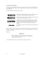
Conventions for Alert Messages This manual uses the following conventions to show the alert ends. The following is an example: (Example) IMPORTANT HA (host adapter) consists of address decoder, driver, and receiver. ATA is an abbreviation of "AT attachment". The disk drive is conformed to the - Fujitsu MPD3173AT | Product Manual - Page 6
defects that involve adjustment, repair, or replacement. Fujitsu is not liable for any other disk drive defects, such as those caused by user misoperation or mishandling, inappropriate operating environments, defects in the power supply or cable, problems of the host system, or other causes outside - Fujitsu MPD3173AT | Product Manual - Page 7
This page is intentionally left blank. - Fujitsu MPD3173AT | Product Manual - Page 8
CONTENTS page CHAPTER 1 DEVICE OVERVIEW 1 - 1 1.1 Features ...1 - 1 1.1.1 Functions and performance 1 - 1 1.1.2 Adaptability...1 - 2 1.1.3 Interface...1 - 2 1.2 Device Specifications ...1 - 4 1.2.1 Specifications summary 1 - 4 1.2.2 Model and product number 1 - 5 1.3 Power Requirements...1 - 5 - Fujitsu MPD3173AT | Product Manual - Page 9
3.4 3.4.1 3.4.2 3.4.3 Jumper Settings ...3 - 12 Location of setting jumpers 3 - 12 Factory default setting ...3 - 13 Jumper configuration...3 - 13 CHAPTER 4 THEORY OF DEVICE OPERATION 4 - 1 4.1 Outline...4 - 1 4.2 Subassemblies ...4 - 1 4.2.1 Disk ...4 - 1 4.2.2 Head ...4 - 2 4.2.3 Spindle...4 - - Fujitsu MPD3173AT | Product Manual - Page 10
5.2.1 I/O registers ...5 - 6 5.2.2 Command block registers 5 - 8 5.2.3 Control block registers 5 - 13 5.3 Host Commands ...5 - 13 5.3.1 Command code and parameters 5 - 14 5.3.2 Command descriptions 5 - 16 5.3.3 Error posting...5 - 66 5.4 Command Protocol...5 - 67 5.4.1 Data transferring commands - Fujitsu MPD3173AT | Product Manual - Page 11
5.6.3.5 Device terminating an Ultra DMA data in burst 5 - 92 5.6.3.6 Host terminating an Ultra DMA data in burst 5 - 93 5.6.3.7 Initiating an Ultra DMA data out burst 5 - 94 5.6.3.8 Sustained Ultra DMA data out burst 5 - 95 5.6.3.9 Device pausing an Ultra DMA data out burst 5 - 96 5.6.3.10 Host - Fujitsu MPD3173AT | Product Manual - Page 12
...3 - 2 3.2 Orientation...3 - 3 3.3 Limitation of side-mounting 3 - 4 3.4 Mounting frame structure 3 - 4 3.5 Surface temperature measurement points 3 - 5 3.6 Service area ...3 - 6 3.7 Connector locations...3 - 7 3.8 Cable connections...3 - 8 3.9 Power supply connector pins (CN1 3 - 9 3.10 Cable - Fujitsu MPD3173AT | Product Manual - Page 13
5.3 Protocol for command abort 5 - 69 5.4 WRITE SECTOR(S) command protocol 5 - 70 5.5 Protocol for the command execution without data transfer 5 - 71 5.6 Normal DMA data transfer 5 - 73 5.7 Ultra DMA termination with pull-up or pull-down 5 - 84 5.8 PIO data transfer timing 5 - 85 5.9 Multiword - Fujitsu MPD3173AT | Product Manual - Page 14
TABLES page 1.1 Specifications ...1 - 4 1.2 Model names and product numbers 1 - 5 1.3 Current and power dissipation 1 - 6 1.4 Environmental specifications 1 - 8 1.5 Acoustic noise specification 1 - 8 1.6 Shock and vibration specification 1 - 9 3.1 Surface temperature measurement points and - Fujitsu MPD3173AT | Product Manual - Page 15
This page is intentionally left blank. - Fujitsu MPD3173AT | Product Manual - Page 16
GB to 17.30 GB respectively. (3) High-speed Transfer rate The disk drive has an internal data rate up to 26.1 MB/s. The disk drive supports an external data rate up to 16.7 MB/s or 66.6 MB/s (ultra DMA mode 4). C141-E069-02EN 1 - 1 - Fujitsu MPD3173AT | Product Manual - Page 17
wide temperature range (5°C to 55°C). (3) Low noise and vibration In Ready status, the noise of the disk drive is only about 3.7 bels (MPD3173AT, Typical Sound Power per ISO7779 and ISO9296). 1.1.3 Interface (1) Connection to interface With the built-in ATA interface controller, the disk drive can - Fujitsu MPD3173AT | Product Manual - Page 18
(5) Error correction and retry by ECC If a recoverable error occurs, the disk drive itself attempts error recovery. The 40 bytes ECC has improved buffer error correction for correctable data errors. (6) Write cache When the disk drive receives a write command, the disk drive posts the command - Fujitsu MPD3173AT | Product Manual - Page 19
mode (normal BIOS specification), formatted capacity, number of cylinders, number of heads, and number of sectors are as follows. Model MPD3043AT MPD3064AT MPD3084AT MPD3108AT MPD3130AT MPD3173AT Formatted Capacity 4,325.52 MB 6,488.29 MB 8,455.20 MB 10,800.85 MB 13,021.10 MB 17,302.13 MB No. of - Fujitsu MPD3173AT | Product Manual - Page 20
CA05177-B351 Ultra DMA mode 2 support CA05177-B99500UW Ultra DMA mode 4 support MPD3130AT 13.02 GB No. 6-32UNC CA05177-B361 Ultra DMA mode 2 support CA05177-B99600UW Ultra DMA mode 4 support MPD3173AT 17.30 GB No. 6-32UNC CA05177-B381 Ultra DMA mode 2 support CA05177-B99800UW Ultra DMA mode - Fujitsu MPD3173AT | Product Manual - Page 21
(3) Current Requirements and Power Dissipation Table 1.3 lists the current and power dissipation. Table 1.3 Current and power dissipation Mode of Operation Typical RMS current (*1) [mA] +12 V +5 V Typical Power (*2) [watts] Model MPD3043 MPD3064/ MPD3108/ MPD3173 All Models MPD3043 MPD3064/ - Fujitsu MPD3173AT | Product Manual - Page 22
(4) Current fluctuation (Typ.) when power is turned on [A] 0.5 0.0 +5VDC 1 (0.5A/div) [A] 1.5 1.0 0.5 +12VDC 2 (0.5A/div) 0.0 0 1 2 3 4 5 6 7 8 [seconds] Note: Maximum current is 1.9 A. Figure 1.1 Current fluctuation (Typ.) when power is turned on (5) Power on/off sequence The voltage - Fujitsu MPD3173AT | Product Manual - Page 23
Sound Power per ISO 7779 and ISO9296 (Typical at 1m) Model Idle mode (DRIVE READY) MPD3043AT MPD3064AT MPD3084AT MPD3108AT MPD3130AT MPD3173AT 3.4 bels 3.5 bels 3.6 bels 3.7 bels Seek mode (Random) 4.0 bels 4.1 bels 4.2 bels 4.3 bels Sound Pressure (Typical at 1m) Idle mode (DRIVE - Fujitsu MPD3173AT | Product Manual - Page 24
Mean time to repair (MTTR) The mean time to repair (MTTR) is 30 minutes or less, if repaired by a specialist maintenance staff member. (3) Service life In situations where management and handling are correct, the disk drive requires no overhaul for five years when the DE surface temperature is less - Fujitsu MPD3173AT | Product Manual - Page 25
(4) Data assurance in the event of power failure Except for the data block being written to, the data on the disk media is assured in the event of any power supply abnormalities. This does not include power supply abnormalities during disk media initialization (formatting) or processing of defects ( - Fujitsu MPD3173AT | Product Manual - Page 26
CHAPTER 2 DEVICE CONFIGURATION 2.1 Device Configuration 2.2 System Configuration 2.1 Device Configuration Figure 2.1 shows the disk drive. The disk drive consists of a disk enclosure (DE), read/write preamplifier, and controller PCA. The disk enclosure contains the disk media, heads, spindle motors - Fujitsu MPD3173AT | Product Manual - Page 27
model, as described below. The disks are rated at over 40,000 start/stop operations. MPD3043AT: 1 disk MPD3064AT, MPD3084AT: 2 disks MPD3108AT, MPD3130AT: 3 disks MPD3173AT: 4 disks (2) Head The heads are of the contact start/stop (CSS) type. The head touches the disk surface while the disk is not - Fujitsu MPD3173AT | Product Manual - Page 28
2.2 System Configuration 2.2.1 ATA interface Figures 2.2 and 2.3 show the ATA interface system configuration. The drive has a 40-pin PC AT interface connector and supports the PIO transfer till 16.7 MB/s (PIO mode 4), the DMA transfer till 16.7 MB/s (Multiword DMA mode 2), and the ultra DMA transfer - Fujitsu MPD3173AT | Product Manual - Page 29
IMPORTANT HA (host adapter) consists of address decoder, driver, and receiver. ATA is an abbreviation of "AT attachment". The disk drive is conformed to the ATA-4 interface. At high speed data transfer (PIO mode 3, - Fujitsu MPD3173AT | Product Manual - Page 30
CHAPTER 3 INSTALLATION CONDITIONS 3.1 Dimensions 3.2 Mounting 3.3 Cable Connections 3.4 Jumper Settings 3.1 Dimensions Figure 3.1 illustrates the dimensions of the disk drive and positions of the mounting screw holes. All dimensions are in mm. C141-E069-02EN 3 - 1 - Fujitsu MPD3173AT | Product Manual - Page 31
Figure 3.1 Dimensions 3 - 2 C141-E069-02EN - Fujitsu MPD3173AT | Product Manual - Page 32
3.2 Mounting (1) Orientation Figure 3.2 illustrates normal orientation for the disk drive. The disk drives can be mounted in any orientation. Horizontal mounting with the PCB facing down Figure 3.2 Orientation (2) Frame The disk enclosure (DE) body is connected to signal ground (SG) and the - Fujitsu MPD3173AT | Product Manual - Page 33
Use these screw holes Do not use this screw holes Figure 3.3 Limitation of side-mounting Bottom surface mounting DE 2 A Frame of system cabinet 2.5 Side surface 2.5 mounting DE 2.5 PCA B Frame of system cabinet 4.5 or less Screw 5.0 or less Details of A Screw Details of B Figure 3.4 - Fujitsu MPD3173AT | Product Manual - Page 34
(4) Ambient temperature The temperature conditions for a disk drive mounted in a cabinet refer to the ambient temperature at a point 3 cm from the disk drive. Pay attention to the air flow to prevent the DE surface temperature from exceeding 60°C. Provide air circulation in the cabinet such that the - Fujitsu MPD3173AT | Product Manual - Page 35
areas) during and after installation. - Mounting screw hole [Q side] - Mounting screw hole [P side] - Cable connection - Mode setting switches Figure 3.6 Service area [R side] - Mounting screw hole (6) External magnetic fields Avoid mounting the disk drive near strong magnetic sources such as - Fujitsu MPD3173AT | Product Manual - Page 36
3.3 Cable Connections 3.3.1 Device connector The disk drive has the connectors and terminals listed below for connecting external devices. Figure 3.7 shows the locations of these connectors and terminals. • Power supply connector (CN1) • ATA interface connector (CN1) Power supply connector (CN1) - Fujitsu MPD3173AT | Product Manual - Page 37
Fujitsu AMP AMP Note : The cable of twisted pairs and neighboring line separated individually is not allowed to use for the host interface cable. It is because that the location of signal lines in these cables is not fixed, and so the problem on the crosstalk among signal lines may occur. It - Fujitsu MPD3173AT | Product Manual - Page 38
Power supply connector pins (CN1) 3.3.5 System configuration for Ultra DMA Host system that support Ultra DMA transfer modes greater than mode 2 shall not share I/O ports. They shall provide separate drivers and separate receivers for each cable. a) The 80-conductor cable assemblies shall be used - Fujitsu MPD3173AT | Product Manual - Page 39
34 Conductor being cut Position 1 Pin 34 contact (PDIAG-:CBLID- signal) System Board Connector Connector 1 Figure 3.10 Cable configuration Connector 2 b) Host system that do not support Ultra DMA modes greater than mode 2 shall not connect to the PDIAG-:CBLID- signal. c) Host system that do - Fujitsu MPD3173AT | Product Manual - Page 40
Host detected CBLID- above VIH PDIAG-: CBLID- conductor Host detected CBLID- below VIL open PDIAG-: CBLID- conductor Host Device 1 Device 0 Host Device 1 Device 0 with 40-conductor cable with 80-conductor cable Figure 3.11 Cable type detection using CBLID- signal (Host sensing the - Fujitsu MPD3173AT | Product Manual - Page 41
3.4 Jumper Settings 3.4.1 Location of setting jumpers Figure 3.13 shows the location of the jumpers to select drive configuration and functions. DC Power Connector 2 Interface Connector 40 3 - 12 1 1 Figure 3.13 Jumper location C141-E069-02EN - Fujitsu MPD3173AT | Product Manual - Page 42
3.4.2 Factory default setting Figure 3.14 shows the default setting position at the factory. (Master device setting) DC Power Connector Interface Connector Figure 3.14 Factory default setting 3.4.3 Jumper configuration (1) Device type Master device (device #0) or slave device (device #1) is - Fujitsu MPD3173AT | Product Manual - Page 43
2 468 1 3579 CSEL connected to the interface cable selection can be done by the special interface cable. Figure 3.16 Jumper setting of Cable Select Figures 3.17 and 3.18 show examples of cable selection using unique interface cables. By connecting the CSEL of the master device to the CSEL Line ( - Fujitsu MPD3173AT | Product Manual - Page 44
jumper settings should be applied. 2 468 2 468 2 468 1 357 9 Master Device 1 357 9 Slave Device 1 357 9 Cable Select Model MPD3043AT MPD3064AT MPD3084AT MPD3108AT MPD3130AT MPD3173AT No. of cylinders 4,092 4,092 4,092 4,092 4,092 4,092 No. of heads 16 16 16 16 16 16 No. of sectors 63 63 63 - Fujitsu MPD3173AT | Product Manual - Page 45
This page is intentionally left blank. - Fujitsu MPD3173AT | Product Manual - Page 46
disks with an outer diameter of 95 mm. The MPD3043AT has 1 disk. The MPD3064AT and MPD3084AT have 2 disks. The MPD3108AT and MPD3130AT have 3 disks. The MPD3173AT has 4 disks. The head contacts the disk each time the disk rotation stops; the life of the disk is 40,000 contacts or more. Servo - Fujitsu MPD3173AT | Product Manual - Page 47
4.2.2 Head Figure 4.1 shows the read/write head structures. The Numerals 0 to 7 indicate read/write heads. These heads are raised from the disk surface as the spindle motor approaches the rated rotation speed. 4 - 2 C141-E069-02EN - Fujitsu MPD3173AT | Product Manual - Page 48
MPD3043AT Model Spindle Actuator 1 0 MPD3064AT Model Spindle 2 1 0 MPD3108AT Model Spindle 4 3 2 1 0 MPD3173AT Model Spindle 7 6 5 4 3 2 1 0 Actuator MPD3084AT Model Spindle Actuator 3 2 1 0 MPD3130AT Model Spindle 5 4 3 2 1 0 Actuator Figure 4.1 Head structure Actuator Actuator C141-E069 - Fujitsu MPD3173AT | Product Manual - Page 49
4.2.3 Spindle The spindle consists of a disk stack assembly and spindle motor. The disk stack assembly is activated by the direct drive sensor-less DC spindle motor, which has a speed of 5,400 rpm. The spindle is controlled with detecting a PHASE signal generated by counter electromotive voltage of - Fujitsu MPD3173AT | Product Manual - Page 50
signal converted to digital for processing by a MPU and then reconverted to an analog signal for control of the voice coil motor. (3) Spindle motor driver circuit The circuit measures the interval of a PHASE signal generated by counter-electromotive voltage of a motor, or servo mark at the MPU and - Fujitsu MPD3173AT | Product Manual - Page 51
Figure 4.2 MPD3xxxAT Block diagram 4 - 6 C141-E069-02EN - Fujitsu MPD3173AT | Product Manual - Page 52
4.4 Power-on Sequence Figure 4.3 describes the operation sequence of the disk drive at power-on. The outline is described below. a) After the power is turned on, the disk drive executes the MPU bus test, internal register read/write test, and work RAM read/write test. When the self-diagnosis - Fujitsu MPD3173AT | Product Manual - Page 53
Power on Start a) Self-diagnosis 1 • MPU bus test • Inner register write/read test • Work RAM write/read test The spindle motor starts. b) Self-diagnosis 2 • Data buffer write/read test c) Confirming spindle motor speed Release heads from actuator lock d) Initial on-track and read out of system - Fujitsu MPD3173AT | Product Manual - Page 54
4.5 Self-calibration The disk drive occasionally performs self-calibration in order to sense and calibrate mechanical external forces on the actuator, and VCM torque. This enables precise seek and read/write operations. 4.5.1 Self-calibration contents (1) Sensing and compensating for external forces - Fujitsu MPD3173AT | Product Manual - Page 55
to the timechart, the disk drive terminates self-calibration and starts executing the command precedingly. In other words, if a disk read or write service is necessary, the disk drive positions the head to the track requested by the host, reads or writes data, and restarts calibration. This enables - Fujitsu MPD3173AT | Product Manual - Page 56
4.6 Read/write Circuit The read/write circuit consists of the read/write preamplifier (PreAMP), the write circuit, the read circuit, and the time base generator in the read channel (RDC). Figure 4.4 is a block diagram of the read/write circuit. 4.6.1 Read/write preamplifier (PreAMP) One PreAMP is - Fujitsu MPD3173AT | Product Manual - Page 57
4 - 12 Figure 4.4 Read/write circuit block diagram C141-E069-02EN - Fujitsu MPD3173AT | Product Manual - Page 58
read signal. Cut-off frequency of the low-pass filter and boost-up gain are controlled from each DAC circuit in read channel by an instruction of the serial data signal from MPU (M1). The MPU optimizes the cut-off frequency and boost-up gain according to the transfer frequency of - Fujitsu MPD3173AT | Product Manual - Page 59
4.6.4 Time base generator circuit The drive uses constant density recording to increase total capacity. This is different from the conventional method of recording data with a fixed data transfer rate at all data area. In the constant density recording method, data area is divided into zones by - Fujitsu MPD3173AT | Product Manual - Page 60
Position Sense SVC (4) (5) DAC P. Amp. VCM current CSR VCM CSR: Current Sense Resistor VCM: Voice Coil Motor (6) Spindle motor control (7) Driver Spindle motor Figure 4.5 Block diagram of servo control circuit (1) Microprocessor unit (MPU) The MPU includes DSP unit, etc., and the MPU - Fujitsu MPD3173AT | Product Manual - Page 61
c. Seek to specified cylinder Drives the VCM to position the head to the specified cylinder. d. Calibration Senses and stores the thermal offset between heads and the mechanical forces on the actuator, and stores the calibration value. Servo frame (96 servo frames per revolution) Figure 4.6 - Fujitsu MPD3173AT | Product Manual - Page 62
, compares with the target revolution speed, then flows the current into the motor coil according to the differentiation (aberration). (7) Driver circuit The driver circuit is a power amplitude circuit that receives signals from the spindle motor control circuit and feeds currents to the spindle - Fujitsu MPD3173AT | Product Manual - Page 63
4.7.2 Data-surface servo format Figure 4.6 describes the physical layout of the servo frame. The three areas indicated by (1) to (3) in Figure 4.6 are described below. (1) Inner guard band The head is in contact with the disk in this space when the spindle starts turning or stops, and the rotational - Fujitsu MPD3173AT | Product Manual - Page 64
2.80 µs 0.45 µs 2.85 µs 0.60 µs 1.80 µs 1.80 µs 1.80 µs 1.80 µs 0.60 µs Write/read Recovery SMK1 Gray Code SMK2 POS A POS B POS C POS PAD D 14.50 µs Servo Frame DATA 115.7 µs DATA Servo Frame DATA Figure 4.7 Servo frame format (1) Write/read recovery This area is used to absorb the write - Fujitsu MPD3173AT | Product Manual - Page 65
control starts. (2) Seek operation Upon a data read/write request from the host, the MPU confirms the necessity of access to the disk. If a read or instruction is issued, the MPU seeks the desired track. 4 - 20 C141-E069-02EN - Fujitsu MPD3173AT | Product Manual - Page 66
the spindle motor, and the 3-phase full/halfwave analog current control circuit is used as the spindle motor driver (called SVC hereafter). The firmware operates on the MPU manufactured by Fujitsu. The spindle motor is controlled by sending several signals from the MPU to the SVC. There are three - Fujitsu MPD3173AT | Product Manual - Page 67
(2) Acceleration mode In this mode, the MPU stops to send the phase switching signal to the SVC. The SVC starts a phase switching by itself based on the counter electromotive force. Then, rotation of the spindle motor accelerates. The MPU calculates a rotational speed of the spindle motor based on - Fujitsu MPD3173AT | Product Manual - Page 68
CHAPTER 5 INTERFACE 5.1 Physical Interface 5.2 Logical Interface 5.3 Host Commands 5.4 Command Protocol 5.5 Ultra DMA feature set 5.6 Timing C141-E069-02EN 5 - 1 - Fujitsu MPD3173AT | Product Manual - Page 69
5.1 Physical Interface 5.1.1 Interface signals Table 5.1 shows the interface signals. Table 5.1 Interface signals Description Cable select Chip select 0 Chip select 1 Data bus bit 0 Data bus bit 1 Data bus bit 2 Data bus bit 3 Data bus bit 4 Data bus bit 5 Data bus bit 6 Data bus bit 7 Data bus - Fujitsu MPD3173AT | Product Manual - Page 70
5.1.2 Signal assignment on the connector Table 5.2 shows the signal assignment on the interface connector. Table 5.2 Signal assignment on the interface connector Pin No. 1 3 5 7 9 11 13 15 17 19 21 23 25 27 29 31 33 35 37 39 Signal RESET- DATA7 DATA6 DATA5 DATA4 DATA3 DATA2 DATA1 DATA0 GND DMARQ - Fujitsu MPD3173AT | Product Manual - Page 71
[signal] DIOR- HDMARDY- HSTROBE INTRQ CS0- CS1- DA 0-2 KEY PIDAG- CBLID- DASP- [I/O] [Description] I DIOR- is the strobe signal asserted by the host to read device registers or the data port. I HDMARDY- is a flow control signal for Ultra DMA data in bursts. This signal is asserted by the host to - Fujitsu MPD3173AT | Product Manual - Page 72
[signal] IORDY DDMARDY- DSTROBE CSEL DMACK- DMARQ GND [I/O] [Description] O This signal is negated to extend the host transfer cycle of any host register access (Read or Write) when the device is not ready to respond to a data transfer request. O DDMARDY- is a flow control signal for Ultra DMA - Fujitsu MPD3173AT | Product Manual - Page 73
execution in either address-specified mode; cylinderhead-sector (CHS) or Logical block address (LBA) mode. The IDENTIFY DEVICE information indicates whether the device supports the LBA mode. When the host system specifies the LBA mode by setting bit 6 in the Device/Head register to 1, HS3 to HS0 - Fujitsu MPD3173AT | Product Manual - Page 74
Table 5.3 I/O registers CS0- CS1- DA2 DA1 I/O registers DA0 Read operation Write operation Command block registers 1 0 0 0 0 Data Data 1 0 0 0 1 Error Register Features 1 0 0 1 0 Sector Count Sector Count 1 0 0 1 1 Sector Number Sector Number 1 0 1 0 0 Cylinder - Fujitsu MPD3173AT | Product Manual - Page 75
5.2.2 Command block registers (1) Data register (X'1F0') The Data register is a 16-bit register for data block transfer between the device and the host system. Data transfer mode is PIO or LBA mode. (2) Error register (X'1F1') The Error register indicates the status of the command executed by the - Fujitsu MPD3173AT | Product Manual - Page 76
[Diagnostic code] X'01': No Error Detected. X'02': HDC Register Compare Error X'03': Data Buffer Compare Error. X'05': ROM Sum Check Error. X'80': Device 1 (slave device) Failed. Error register of the master device is valid under two devices (master and slave) configuration. If the slave - Fujitsu MPD3173AT | Product Manual - Page 77
(6) Cylinder Low register (X'1F4') The contents of this register indicates low-order 8 bits of the starting cylinder address for any disk-access. At the end of a command, the contents of this register are updated to the current cylinder number. Under the LBA mode, this register indicates LBA bits 15 - Fujitsu MPD3173AT | Product Manual - Page 78
(9) Status register (X'1F7') The contents of this register indicate the status of the device. The contents of this register are updated at the completion of each command. When the BSY bit is cleared, other bits in this register should be validated within 400 ns. When the BSY bit is 1, other bits of - Fujitsu MPD3173AT | Product Manual - Page 79
- Bit 3: - Bit 2: - Bit 1: - Bit 0: Data Request (DRQ) bit. This bit indicates that the device is ready to transfer data of word unit or byte unit between the host system and the device. Always 0. Always 0. Error (ERR) bit. This bit indicates that an error was detected while the previous command - Fujitsu MPD3173AT | Product Manual - Page 80
5.2.3 Control block registers (1) Alternate Status register (X'3F6') The Alternate Status register contains the same information as the Status register of the command block register. The only difference from the Status register is that a read of this register does not imply Interrupt Acknowledge and - Fujitsu MPD3173AT | Product Manual - Page 81
5.3.1 Command code and parameters Table 5.4 lists the supported commands, command code and the registers that needed parameters are written. Table 5.4 Command code and parameters (1 of 2) Command name READ SECTOR(S) READ MULTIPLE READ DMA - Fujitsu MPD3173AT | Product Manual - Page 82
Table 5.4 Command code and parameters (2 of 2) Command name STANDBY IMMEDIATE SLEEP CHECK POWER MODE SMART FLUSH CACHE SECURITY DISABLE PASSWORD SECURITY ERASE PREPARE SECURITY ERASE UNIT SECURITY FREEZE LOCK SECURITY SET PASSWORD SECURITY UNLOCK SET MAX ADDRESS READ NATIVE MAX ADDRESS Command - Fujitsu MPD3173AT | Product Manual - Page 83
5.3.2 Command descriptions The contents of the I/O registers to be necessary for issuing a command and the example indication of the I/O registers at command completion are shown as following in this subsection. Example: READ SECTOR(S) At command issuance (I/O registers setting contents) Bit - Fujitsu MPD3173AT | Product Manual - Page 84
Note: 1. When the L bit is specified to 1, the lower 4 bits of the DH register and all bits of the CH, CL and SN registers indicate the LBA bits (bits of the DH register are the MSB (most significant bit) and bits of the SN register are the LSB (least significant bit). 2. At error occurrence, the SC - Fujitsu MPD3173AT | Product Manual - Page 85
At command completion (I/O registers contents to be read) 1F7H(ST) 1F6H(DH) Status information × L × DV End head No. /LBA [MSB] 1F5H(CH) 1F4H(CL) 1F3H(SN) 1F2H(SC) 1F1H(ER) End cylinder No. [MSB] / LBA End cylinder No. [LSB] / LBA End sector No. / LBA [LSB] 00 (*1) Error information *1 If - Fujitsu MPD3173AT | Product Manual - Page 86
Figure 5.1 shows an example of the execution of the READ MULTIPLE command. • Block count specified by SET MULTIPLE MODE command = 4 (number of sectors in a block) • READ MULTIPLE command specifies; Number of requested sectors = 9 (Sector Count register = 9) ↓ Number of sectors in incomplete block = - Fujitsu MPD3173AT | Product Manual - Page 87
(3) READ DMA (X'C8' or X'C9') This command operates similarly to the READ SECTOR(S) command except for following events. • The data transfer starts at the timing of DMARQ signal assertion. • The device controls the assertion or negation timing of the DMARQ signal. • The device posts a status as the - Fujitsu MPD3173AT | Product Manual - Page 88
At command completion (I/O registers contents to be read) 1F7H(ST) Status information 1F6H(DH) × L × DV End head No. /LBA [MSB] 1F5H(CH) 1F4H(CL) 1F3H(SN) 1F2H(SC) 1F1H(ER) End cylinder No. [MSB] / LBA End cylinder No. [LSB] / LBA End sector No. / LBA [LSB] 00 (*1) Error information *1 - Fujitsu MPD3173AT | Product Manual - Page 89
At command completion (I/O registers contents to be read) 1F7H(ST) Status information 1F6H(DH) × L × DV End head No. /LBA [MSB] 1F5H(CH) 1F4H(CL) 1F3H(SN) 1F2H(SC) 1F1H(ER) End cylinder No. [MSB] / LBA End cylinder No. [LSB] / LBA End sector No. / LBA [LSB] 00 (*1) Error information *1 - Fujitsu MPD3173AT | Product Manual - Page 90
At command completion (I/O registers contents to be read) 1F7H(ST) Status information 1F6H(DH) × L × DV End head No. /LBA [MSB] 1F5H(CH) 1F4H(CL) 1F3H(SN) 1F2H(SC) 1F1H(ER) End cylinder No. [MSB] / LBA End cylinder No. [LSB] / LBA End sector No. / LBA [LSB] 00 (*1) Error information *1 - Fujitsu MPD3173AT | Product Manual - Page 91
The contents of the command block registers related to addresses after the transfer of a data block containing an erred sector are undefined. To obtain a valid error information, the host should retry data transfer as an individual requests. At command issuance (I/O registers setting contents) - Fujitsu MPD3173AT | Product Manual - Page 92
1) Multiword DMA transfer mode 2: Sets the FR register = X'03' and SC register = X'22' by the SET FEATURES command 2) Ultra DMA transfer mode 2: Sets the FR register = X'03' and SC register = X'42' by the SET FEATURES command At command issuance (I/O registers setting contents) 1F7H(CM) 1 1 0 - Fujitsu MPD3173AT | Product Manual - Page 93
At command completion (I/O registers contents to be read) 1F7H(ST) Status information 1F6H(DH) × L × DV End head No. /LBA [MSB] 1F5H(CH) 1F4H(CL) 1F3H(SN) 1F2H(SC) 1F1H(ER) End cylinder No. [MSB] / LBA End cylinder No. [LSB] / LBA End sector No. / LBA [LSB] 00 (*1) Error information *1 - Fujitsu MPD3173AT | Product Manual - Page 94
(10) SEEK (X'7x', x : X'0' to X'F') This command performs a seek operation to the track and selects the head specified in the command block registers. After completing the seek operation, the device clears the BSY bit in the Status register and generates an interrupt. The IDD always sets the DSC bit - Fujitsu MPD3173AT | Product Manual - Page 95
(11) INITIALIZE DEVICE PARAMETERS (X'91') The host system can set the number of sectors per track and the maximum head number (maximum head number is "number of heads minus 1") per cylinder with this command. Upon receipt of this command, the device sets the BSY bit of Status register and saves the - Fujitsu MPD3173AT | Product Manual - Page 96
At command issuance (I/O registers setting contents) 1F7H(CM) 1 1 1 0 1 1 0 0 1F6H(DH) × × × DV xx 1F5H(CH) xx 1F4H(CL) xx 1F3H(SN) xx 1F2H(SC) xx 1F1H(FR) xx At command completion (I/O registers contents to be read) 1F7H(ST) Status information 1F6H(DH) × × × DV xx 1F5H( - Fujitsu MPD3173AT | Product Manual - Page 97
WRITE MULTIPLE command Total number of user addressable sectors (LBA mode only) Retired Multiword DMA transfer mode *12 Advance PIO transfer mode support status *13 Minimum multiword DMA transfer cycle time per word : 120 [ns] Manufacturer's recommended DMA transfer cycle time : 120 [ns] Minimum PIO - Fujitsu MPD3173AT | Product Manual - Page 98
following model numbers; MPD3043AT, MPD3064AT, MPD3084AT, MPD3108AT, MPD3130AT, MPD3173AT *7 Word 49: Capabilities Bit 15-14: Reserved Bit 13: 11: IORDY support 1=Supported Bit 10: IORDY inhibition 0=Disable inhibition Bit 9: LBA support 1=Supported Bit 8: DMA support 1=Supported Bit 7-0: - Fujitsu MPD3173AT | Product Manual - Page 99
Device Reset command supported = 0 Bit 8: SERVICE Interrupt supported = 0 Bit 7: Release Interrupt supported = 0 Bit 6: Lock Ahead supported = 1 Bit 5: Write-cache supported = 1 Bit 4: Packet command feature set supported = 0 Bit 3: Power Management feature set supported=1 Bit 2: Removable feature - Fujitsu MPD3173AT | Product Manual - Page 100
Bit 15: Reserved Bit 14: NOP command supported = 0 Bit 13: READ BUFFER command supported = 0 Bit 12: WRITE BUFFER command supported = 0 Bit 11: Reserved Bit 10: Host Protected Area feature set supported = 0 Bit 9: DEVICE RESET command supported = 0 Bit 8: SERVICE interrupt enabled = 0 Bit 7: Release - Fujitsu MPD3173AT | Product Manual - Page 101
parameters in the Features register. Then, the device clears the BSY bit, and generates an interrupt. If the value in the Features register is not supported or it is invalid, the device posts an ABORTED COMMAND error. Table 5.6 lists the available values and operational modes that may be set in the - Fujitsu MPD3173AT | Product Manual - Page 102
register values and settable modes Features Register Drive operation mode X'02' Enables the write cache function. X'03' Specifies the transfer mode. Supports PIO mode 4, single word DMA mode 2, and multiword DMA mode regardless of Sector Count register contents. X'04' No operation. X'05 - Fujitsu MPD3173AT | Product Manual - Page 103
with the PIO transfer mode 4 and multiword DMA transfer mode 2 regardless of reception of the SET FEATURES command for transfer mode setting. The IDD supports following values in the Sector Count register value. If other value than below is specified, an ABORTED COMMAND error is posted. PIO default - Fujitsu MPD3173AT | Product Manual - Page 104
commands are also specified by the SET MULTIPLE MODE command. The number of sectors per block is written into the Sector Count register. The IDD supports 2, 4, 8 and 16 (sectors) as the block counts. Upon receipt of this command, the device sets the BSY bit of the Status register and checks the - Fujitsu MPD3173AT | Product Manual - Page 105
Regarding software reset, the mode set prior to software reset is retained after software reset. The parameters for the multiple commands which are posted to the host system when the IDENTIFY DEVICE command is issued are listed below. See Subsection 5.3.2 for the IDENTIFY DEVICE command. Word 47 = - Fujitsu MPD3173AT | Product Manual - Page 106
BYS bit and generates an interrupt soon. When the command execution completes, the device clears the BSY bit and generates an interrupt. The drive supports this command for keep the compatibility with previous drive only. (18) READ LONG (X'22' or X'23') This command operates similarly to the READ - Fujitsu MPD3173AT | Product Manual - Page 107
the ECC bytes transferred from the host system to the disk medium. The device does not generate ECC bytes by itself. The WRITE LONG command supports only single sector operation. This command is operated under the following conditions: • The command is issued in a sequence of the READ LONG or WRITE - Fujitsu MPD3173AT | Product Manual - Page 108
At command issuance (I/O registers setting contents) 1F7H(CM) 0 0 1 1 0 0 1R 1F6H(DH) × L × DV Head No. /LBA [MSB] 1F5H(CH) 1F4H(CL) 1F3H(SN) 1F2H(SC) 1F1H(FR) R = 0 or 1 Cylinder No. [MSB] / LBA Cylinder No. [LSB] / LBA Sector No. / LBA [LSB] Number of sectors to be transferred xx - Fujitsu MPD3173AT | Product Manual - Page 109
At command completion (I/O registers contents to be read) 1F7H(ST) Status information 1F6H(DH) × × × DV xx 1F5H(CH) 1F4H(CL) 1F3H(SN) 1F2H(SC) 1F1H(ER) xx xx xx xx Error information (21) WRITE BUFFER (X'E8') The host system can overwrite the contents of the sector buffer of the device with a - Fujitsu MPD3173AT | Product Manual - Page 110
(22) IDLE (X'97' or X'E3') Upon receipt of this command, the device sets the BSY bit of the Status register, and enters the idle mode. Then, the device clears the BSY bit, and generates an interrupt. The device generates an interrupt even if the device has not fully entered the idle mode. If the - Fujitsu MPD3173AT | Product Manual - Page 111
of the Status register, and enters the idle mode. Then, the device clears the BSY bit, and generates an interrupt. This command does not support the automatic power-down function. At command issuance (I/O registers setting contents) 1F7H(CM) X'95' or X'E1' 1F6H(DH) × × × DV xx 1F5H(CH) xx - Fujitsu MPD3173AT | Product Manual - Page 112
bit of the Status register and enters the standby mode. The device then clears the BSY bit and generates an interrupt. This command does not support the automatic power-down sequence. C141-E069-02EN 5 - 45 - Fujitsu MPD3173AT | Product Manual - Page 113
At command issuance (I/O registers setting contents) 1F7H(CM) X'94' or X'E0' 1F6H(DH) × × × DV xx 1F5H(CH) xx 1F4H(CL) xx 1F3H(SN) xx 1F2H(SC) xx 1F1H(FR) xx At command completion (I/O registers contents to be read) 1F7H(ST) Status information 1F6H(DH) × × × DV xx 1F5H(CH) 1F4H - Fujitsu MPD3173AT | Product Manual - Page 114
At command completion (I/O registers contents to be read) 1F7H(ST) Status information 1F6H(DH) × × × DV xx 1F5H(CH) 1F4H(CL) 1F3H(SN) 1F2H(SC) 1F1H(ER) xx xx xx xx Error information (27) CHECK POWER MODE (X'98' or X'E5') The host checks the power mode of the device with this command. The - Fujitsu MPD3173AT | Product Manual - Page 115
) This command performs operations for device failure predictions according to a subcommand specified in the FR register. If the value specified in the FR register is supported, the Aborted Command error is posted. It is necessary for the host to set the keys (CL = 4Fh and CH = C2h) in the CL and - Fujitsu MPD3173AT | Product Manual - Page 116
Table 5.8 Features Register values (subcommands) and functions Features Resister X'D0' X'D1' X'D2' X'D3' X'D8' X'D9' X'DA' Function SMART Read Attribute Values: A device that received this subcommand asserts the BSY bit and saves all the updated attribute values. The device then clears the BSY bit - Fujitsu MPD3173AT | Product Manual - Page 117
Alternative, the device must issue the SMART Enable-Disable Attribute AutoSave subcommand (FR register = D2h) to use a feature which regularly save the device attribute value data to a medium. The host can predict failures in the device by periodically issuing the SMART Return Status subcommand (FR - Fujitsu MPD3173AT | Product Manual - Page 118
The attribute value information is 512-byte data; the format of this data is shown below. The host can access this data using the SMART Read Attribute Values subcommand (FR register = D0h). The insurance failure threshold value data is 512-byte data; the format of this data is shown below. The host - Fujitsu MPD3173AT | Product Manual - Page 119
Table 5.10 Format of insurance failure threshold value data Byte Item 00 Data format version number 01 02 Attribute 1 Attribute ID 03 Insurance failure threshold 04 Threshold 1 (Threshold of Reserved attribute 1) to 0D 0E Threshold 2 to (The format of each threshold value is the - Fujitsu MPD3173AT | Product Manual - Page 120
• Attribute ID The attribute ID is defined as follows: Attribute ID Attribute name 0 (Indicates unused attribute data.) 1 Read error rate 2 Throughput performance 3 Spin up time 4 Number of times the spindle motor is activated 5 Number of alternative sectors 7 Seek error rate 8 - Fujitsu MPD3173AT | Product Manual - Page 121
• Raw attribute value Raw attributes data is retained. • Failure prediction capability flag Bit 0: The attribute value data is saved to a medium before the device enters power saving mode. Bit 1: The device automatically saves the attribute value data to a medium after the previously set operation. - Fujitsu MPD3173AT | Product Manual - Page 122
data to be flushed and the success of the operation. NOTE - This command may take longer than 30 s to complete. If the command is not supported, the device shall set the ABRT bit to one. An unrecoverable error encountered during execution of writing data results in the termination of the command - Fujitsu MPD3173AT | Product Manual - Page 123
(30) SECURITY DISABLE PASSWORD (F6h) This command invalidates the user password already set and releases the lock function. The host transfers the 512-byte data shown in Table 1.1 to the device. The device compares the user password or master password in the transferred data with the user password - Fujitsu MPD3173AT | Product Manual - Page 124
At command issuance (I-O registers setting contents) 1F7H(CM) 1 1 1 1 0 1 1 0 1F6H(DH) × × × DV xx 1F5H(CH) xx 1F4H(CL) xx 1F3H(SN) xx 1F2H(SC) xx 1F1H(FR) xx At command completion (I-O registers setting contents) 1F7H(ST) Status information 1F6H(DH) × × × DV xx 1F5H(CH) - Fujitsu MPD3173AT | Product Manual - Page 125
At command issuance (I-O registers setting contents) 1F7H(CM) 1 1 1 1 0 0 1 1 1F6H(DH) × × × DV xx 1F5H(CH) xx 1F4H(CL) xx 1F3H(SN) xx 1F2H(SC) xx 1F1H(FR) xx At command completion (I-O registers setting contents) 1F7H(ST) Status information 1F6H(DH) × × × DV xx 1F5H(CH) - Fujitsu MPD3173AT | Product Manual - Page 126
At command issuance (I-O registers setting contents) 1F7H(CM) 1 1 1 1 0 1 0 0 1F6H(DH) × × × DV xx 1F5H(CH) xx 1F4H(CL) xx 1F3H(SN) xx 1F2H(SC) xx 1F1H(FR) xx At command completion (I-O registers setting contents) 1F7H(ST) Status information 1F6H(DH) × × × DV xx 1F5H(CH) - Fujitsu MPD3173AT | Product Manual - Page 127
• READ DMA • READ LONG • READ MULTIPLE • READ SECTORS • WRITE DMA • WRITE LONG • WRITE MULTIPLE • WRITE SECTORS • WRITE VETIFY • SECURITY DISABLE PASSWORD • SECURITY FREEZE LOCK • SECURITY SET PASSWORD At command issuance (I-O registers setting contents) 1F7H(CM) 1 1 1 1 0 1 0 1 1F6H(DH - Fujitsu MPD3173AT | Product Manual - Page 128
Table 5.12 Contents of SECURITY SET PASSWORD data Word 0 1 to 16 17 to 255 Contents Control word Bit 0 Identifier 0 = Sets a user password. 1 = Sets a master password. Bits 1 to 7 Reserved Bit 8 Security level 0 = High 1 = Maximum Bits 9 to 15 Reserved Password (32 bytes) Reserved Table 5.13 - Fujitsu MPD3173AT | Product Manual - Page 129
At command issuance (I-O registers setting contents) 1F7H(CM) 1 1 1 1 0 0 0 1 1F6H(DH) × × × DV xx 1F5H(CH) xx 1F4H(CL) xx 1F3H(SN) xx 1F2H(SC) xx 1F1H(FR) xx At command completion (I-O registers setting contents) 1F7H(ST) Status information 1F6H(DH) × × × DV xx 1F5H(CH) - Fujitsu MPD3173AT | Product Manual - Page 130
At command issuance (I-O registers setting contents) 1F7H(CM) 1 1 1 1 0 0 1 0 1F6H(DH) × × × DV xx 1F5H(CH) xx 1F4H(CL) xx 1F3H(SN) xx 1F2H(SC) xx 1F1H(FR) xx At command completion (I-O registers setting contents) 1F7H(ST) Status information 1F6H(DH) × × × DV xx 1F5H(CH) - Fujitsu MPD3173AT | Product Manual - Page 131
At command issuance (I/O registers setting contents) 1F7H(CM) 1 1 1 1 1 0 0 1 1F6H(DH) × L × DV Max head/LBA [MSB] 1F5H(CH) 1F4H(CL) 1F3H(SN) Max. cylinder [MSB]/Max. LBA Max. cylinder [LSB]/Max. LBA Max. sector/Max. LBA [LSB] 1F2H(SC) xx VV 1F1H(FR) xx At command completion (I/O - Fujitsu MPD3173AT | Product Manual - Page 132
At command completion (I/O registers contents to be read) 1F7H(ST) Status information 1F6H(DH) × × × DV Max head/LBA [MSB] 1F5H(CH) 1F4H(CL) 1F3H(SN) 1F2H(SC) 1F1H(ER) Max. cylinder [MSB]/Max. LBA Max. cylinder [LSB]/Max. LBA Max. sector/Max. LBA [LSB] xx Error information C141-E069-02EN 5 - - Fujitsu MPD3173AT | Product Manual - Page 133
5.3.3 Error posting Table 5.14 lists the defined errors that are valid for each command. Table 5.14 Command code and parameters Command name READ SECTOR(S) WRITE SECTOR(S) READ MULTIPLE WRITE MULTIPLE READ DMA WRITE DMA WRITE VERIFY READ VERIFY SECTOR(S) RECALIBRATE SEEK INITIALIZE DEVICE - Fujitsu MPD3173AT | Product Manual - Page 134
5.4 Command Protocol The host should confirm that the BSY bit of the Status register of the device is 0 prior to issue a command. If BSY bit is 1, the host should wait for issuing a command until BSY bit is cleared to 0. Commands can be executed only when the DRDY bit of the Status register is 1. - Fujitsu MPD3173AT | Product Manual - Page 135
Command Parameter write ~ bc a BSY DRDY d DRQ Status read e f d Status read e INTRQ Data transfer Expanded Command Min. 30 µs (*1) DRQ INTRQ Data Reg. Selection Data IOR- Word 0 1 IOCS16- • • • 2 255 *1 When the IDD receives a command that hits the cache data - Fujitsu MPD3173AT | Product Manual - Page 136
Note: For transfer of a sector of data, the host needs to read Status register (X'1F7') in order to clear INTRQ (interrupt) signal. The Status register should be read within a period from the DRQ setting by the device to 5 µs after the completion of the sector data transfer. Note that the host does - Fujitsu MPD3173AT | Product Manual - Page 137
a) The host writes any required parameters to the Features, Sector Count, Sector Number, Cylinder, and Device/Head registers. b) The host writes a command code in the Command register. The drive sets the BSY bit of the Status register. c) When the device is ready to receive the data of the first - Fujitsu MPD3173AT | Product Manual - Page 138
Note: For transfer of a sector of data, the host needs to read Status register (X'1F7') in order to clear INTRQ (interrupt) signal. The Status register should be read within a period from the DRQ setting by the device to 5 µs after the completion of the sector data transfer. Note that the host does - Fujitsu MPD3173AT | Product Manual - Page 139
5.4.4 Other commands • READ MULTIPLE • SLEEP • WRITE MULTIPLE See the description of each command. 5.4.5 DMA data transfer commands • READ DMA • WRITE DMA Starting the DMA transfer command is the same as the READ SECTOR(S) or WRITE SECTOR(S) command except the point that the host initializes the DMA - Fujitsu MPD3173AT | Product Manual - Page 140
Parameter write Command ~ c, d a BSY • • DRDY INTRQ DRQ Data transfer e • • • • Status read f g Expanded [Multiword DMA transfer] DRQ DMARQ DMACK- IOR- or IOW- Word 0 1 n-1 n Figure 5.6 Normal DMA data transfer C141-E069-02EN 5 - 73 - Fujitsu MPD3173AT | Product Manual - Page 141
time. All timing requirements for a selected Ultra DMA Mode shall be satisfied. Devices supporting Ultra DMA Mode 2 shall also support Ultra DMA Modes 0 and 1. Devices supporting Ultra DMA Mode 1 shall also support Ultra DMA Mode 0. An Ultra DMA capable device shall retain its previously selected - Fujitsu MPD3173AT | Product Manual - Page 142
5.5.2 Phases of operation An Ultra DMA data transfer is accomplished through a series of Ultra DMA data in or data out bursts. Each Ultra DMA burst has three mandatory phases of operation: the initiation phase, the data transfer phase, and the Ultra DMA burst termination phase. In addition, an Ultra - Fujitsu MPD3173AT | Product Manual - Page 143
11) The device shall drive the first word of the data transfer onto DD (15:0). This step may occur when the device first drives DD (15:0) in step (10). 12) To transfer the first word of data the device shall negate DSTROBE within tFS after the host has negated STOP and asserted HDMARDY-. The device - Fujitsu MPD3173AT | Product Manual - Page 144
3) The device shall stop generating DSTROBE edges within tRFS of the host negating HDMARDY-. 4) If the host negates HDMARDY- within tSR after the device has generated a DSTROBE edge, then the host shall be prepared to receive zero or one additional data words. If the host negates HDMARDY- greater - Fujitsu MPD3173AT | Product Manual - Page 145
10) The device shall latch the host's CRC data from DD (15:0) on the negating edge of DMACK-. 11) The device shall compare the CRC data received from the host with the results of its own CRC calculation. If a miscompare error occurs during one or more Ultra DMA bursts for any one command, at the end - Fujitsu MPD3173AT | Product Manual - Page 146
10) If the host has not placed the result of its CRC calculation on DD (15:0) since first driving DD (15:0) during (9), the host shall place the result of its CRC calculation on DD (15:0) (see 5.5.5). 11) The host shall negate DMACK- no sooner than tMLI after the device has asserted DSTROBE and - Fujitsu MPD3173AT | Product Manual - Page 147
9) The device shall assert DDMARDY- within tLI after the host has negated STOP. After asserting DMARQ and DDMARDY- the device shall not negate either signal until after the first negation of HSTROBE by the host. 10) The host shall drive the first word of the data transfer onto DD (15:0). This step - Fujitsu MPD3173AT | Product Manual - Page 148
b) Device pausing an Ultra DMA data out burst 1) The device shall not pause an Ultra DMA burst until at least one data word of an Ultra DMA burst has been transferred. 2) The device shall pause an Ultra DMA burst by negating DDMARDY-. 3) The host shall stop generating HSTROBE edges within tRFS of - Fujitsu MPD3173AT | Product Manual - Page 149
9) The device shall compare the CRC data received from the host with the results of its own CRC calculation. If a miscompare error occurs during one or more Ultra DMA bursts for any one command, at the end of the command, the device shall report the first error that occurred (see 5.5.5). 10) The - Fujitsu MPD3173AT | Product Manual - Page 150
11) The device shall compare the CRC data received from the host with the results of its own CRC calculation. If a miscompare error occurs during one or more Ultra DMA bursts for any one command, at the end of the command, the device shall report the first error that occurred (see 5.5.5). 12) The - Fujitsu MPD3173AT | Product Manual - Page 151
I) The CRC generator polynomial is : G (X) = X16 + X12 + X5 + 1. Note: Since no bit clock is available, the recommended approach for calculating CRC is to use a word clock derived from the bus strobe. The combinational logic shall then be equivalent to shifting sixteen bits serially through the - Fujitsu MPD3173AT | Product Manual - Page 152
5.6 Timing 5.6.1 PIO data transfer Figure 5.8 shows of the data transfer timing between the device and the host system. t0 Addresses DIOR-/DIOW- Write data DD0-DD15 t1 t2 t9 t2i t3 t4 Read data DD0-DD15 IORDY t5 t10 t6 t11 t12 Symbol Timing parameter t0 Cycle time t1 Data register - Fujitsu MPD3173AT | Product Manual - Page 153
5.6.2 Multiword data transfer Figure 5.9 shows the multiword DMA data transfer timing between the device and the host system. DMARQ DMACK- DIOR-/DIOW- t0 tC tJ tI tD tK Write data DD0-DD15 tG tH Read data DD0-DD15 tE tF Symbol Timing parameter t0 Cycle time tC Delay time from DMACK - Fujitsu MPD3173AT | Product Manual - Page 154
5.6.3 Ultra DMA data transfer Figures 5.10 through 5.19 define the timings associated with all phases of Ultra DMA bursts. Table 5.16 contains the values for the timings for each of the Ultra DMA Modes. 5.6.3.1 Initiating an Ultra DMA data in burst 5.6.3.2 contains the values for the timings for - Fujitsu MPD3173AT | Product Manual - Page 155
with minimum (see Note 3) 0 Unlimited interlock time (see Note 3) 10 Maximum time allowed for output drivers to release (from asserted or negated) 20 Minimum delay time required for output 0 Drivers to assert or negate (from released) 20 55 Envelope time (from DMACK- to STOP and HDMARDY - Fujitsu MPD3173AT | Product Manual - Page 156
Table 5.16 Ultra DMA data burst timing requirements (2 of 2) NAME MODE 0 (in ns) MODE 1 (in ns) MODE 2 (in ns) MODE 3 (in ns) MODE 4 (in ns) COMMENT MIN MAX MIN MAX MIN MAX MIN MAX MIN MAX (see Notes 1 and 2) tZIORDY 0 0 0 0 0 Minimum time before driving IORDY tACK 20 20 20 20 - Fujitsu MPD3173AT | Product Manual - Page 157
5.6.3.3 Sustained Ultra DMA data in burst 5.6.3.2 contains the values for the timings for each of the Ultra DMA Modes. Note: DD (15:0) and DSTROBE are shown at both the host and the device to emphasize that cable setting time as well as cable propagation delay shall not allow the data signals to be - Fujitsu MPD3173AT | Product Manual - Page 158
5.6.3.4 Host pausing an Ultra DMA data in burst 5.6.3.2 contains the values for the timings for each of the Ultra DMA Modes. Notes: 1) The host may assert STOP to request termination of the Ultra DMA burst no sooner than tRP after HDMARDY- is negated. 2) If the tSR timing is not satisfied, the host - Fujitsu MPD3173AT | Product Manual - Page 159
5.6.3.5 Device terminating an Ultra DMA data in burst 5.6.3.2 contains the values for the timings for each of the Ultra DMA Modes. Note: The definitions for the STOP, HDMARDY- and DSTROBE signal lines are no longer in effect after DMARQ and DMACK are negated. Figure 5.13 Device terminating an Ultra - Fujitsu MPD3173AT | Product Manual - Page 160
5.6.3.6 Host terminating an Ultra DMA data in burst 5.6.3.2 contains the values for the timings for each of the Ultra DMA Modes. Note: The definitions for the STOP, HDMARDY- and DSTROBE signal lines are no longer in effect after DMARQ and DMACK are negated. Figure 5.14 Host terminating an Ultra DMA - Fujitsu MPD3173AT | Product Manual - Page 161
5.6.3.7 Initiating an Ultra DMA data out burst 5.6.3.2 contains the values for the timings for each of the Ultra DMA Modes. Note: The definitions for the STOP, DDMARDY- and HSTROBE signal lines are not in effect until DMARQ and DMACK are asserted. Figure 5.15 Initiating an Ultra DMA data out burst - Fujitsu MPD3173AT | Product Manual - Page 162
5.6.3.8 Sustained Ultra DMA data out burst 5.6.3.2 contains the values for the timings for each of the Ultra DMA Modes. Note: DD (15:0) and HSTROBE signals are shown at both the device and the host to emphasize that cable setting time as well as cable propagation delay shall not allow the data - Fujitsu MPD3173AT | Product Manual - Page 163
5.6.3.9 Device pausing an Ultra DMA data out burst 5.6.3.2 contains the values for the timings for each of the Ultra DMA Modes. Notes: 1) The device may negate DMARQ to request termination of the Ultra DMA burst no sooner than tRP after DDMARDY- is negated. 2) If the tSR timing is not satisfied, - Fujitsu MPD3173AT | Product Manual - Page 164
5.6.3.10 Host terminating an Ultra DMA data out burst 5.6.3.2 contains the values for the timings for each of the Ultra DMA Modes. Note: The definitions for the STOP, DDMARDY- and HSTROBE signal lines are no longer in effect after DMARQ and DMACK are negated. Figure 5.18 Host terminating an Ultra - Fujitsu MPD3173AT | Product Manual - Page 165
5.6.3.11 Device terminating an Ultra DMA data in burst 5.6.3.2 contains the values for the timings for each of the Ultra DMA Modes. Note: The definitions for the STOP, DDMARDY- and HSTROBE signal lines are no longer in effect after DMARQ and DMACK are negated. Figure 5.19 Device terminating an - Fujitsu MPD3173AT | Product Manual - Page 166
5.6.4 Power-on and reset Figure 5.20 shows power-on and reset (hardware and software reset) timing. (1) Only master device is present Clear Reset *1 Power-on RESETSoftware reset BSY tM tN DASPtP *1: Reset means including Power-on-Reset, Hardware Reset (RESET-), and Software Reset. (2) Master - Fujitsu MPD3173AT | Product Manual - Page 167
This page is intentionally left blank. - Fujitsu MPD3173AT | Product Manual - Page 168
CHAPTER 6 OPERATIONS 6.1 Device Response to the Reset 6.2 Address Translation 6.3 Power Save 6.4 Defect Management 6.5 Read-Ahead Cache 6.6 Write Cache 6.1 Device Response to the Reset This section describes how the PDIAG- and DASP- signals responds when the power of the IDD is turned on or the IDD - Fujitsu MPD3173AT | Product Manual - Page 169
6.1.1 Response to power-on After the master device (device 0) releases its own power-on reset state, the master device shall check a DASP- signal for up to 450 ms to confirm presence of a slave device (device 1). The master device recognizes presence of the slave device when it confirms assertion of - Fujitsu MPD3173AT | Product Manual - Page 170
6.1.2 Response to hardware reset Response to RESET- (hardware reset through the interface) is similar to the power-on reset. Upon receipt of hardware reset, the master device checks a DASP- signal for up to 450 ms to confirm presence of a slave device. The master device recognizes the presence of - Fujitsu MPD3173AT | Product Manual - Page 171
6.1.3 Response to software reset The master device does not check the DASP- signal for a software reset. If a slave device is present, the master device checks the PDIAG- signal for up to 31 seconds to see if the slave device has completed the self-diagnosis successfully. After the slave device - Fujitsu MPD3173AT | Product Manual - Page 172
6.1.4 Response to diagnostic command When the master device receives an EXECUTE DEVICE DIAGNOSTIC command and the slave device is present, the master device checks the PDIAG- signal for up to 6 seconds to see if the slave device has completed the self-diagnosis successfully. The master device does - Fujitsu MPD3173AT | Product Manual - Page 173
6.1 Default parameters Number of cylinders Parameters Number of (logical) head Number of sectors/track Formatted capacity (MB) MPD3043AT MPD3064AT MPD3084AT MPD3108AT MPD3130AT MPD3173AT 8,940 13,410 16,383 15 16 4,325.5 6,488.2 63 8,455.2 10,800.8 13,021.1 17,302.1 As long as the - Fujitsu MPD3173AT | Product Manual - Page 174
6.2.2 Logical address (1) CHS mode Logical address assignment starts from physical cylinder (PC) 0, physical head (PH) 0, and physical sector (PS) 1 and is assigned by calculating the number of sectors per track which is specified by the INITIALIZE DEVICE PARAMETERS command. The head address is - Fujitsu MPD3173AT | Product Manual - Page 175
(2) LBA mode Logical address assignment in the LBA mode starts from physical cylinder 0, physical head 0, and physical sector 1. The logical address is advanced at the subsequent sector from the last sector of the current track. The first physical sector of the subsequent physical track is the - Fujitsu MPD3173AT | Product Manual - Page 176
(1) Active mode In this mode, all the electric circuit in the device are active or the device is under seek, read or write operation. A device enters the active mode under the following conditions: • Power-on sequence is completed. • A command other than power commands is issued. • Reset (hardware - Fujitsu MPD3173AT | Product Manual - Page 177
• INITIALIZE DEVICE PARAMETERS command • CHECK POWER MODE command (4) Sleep mode The power consumption of the drive is minimal in this mode. The drive enters only the standby mode from the sleep mode. The only method to return from the standby mode is to execute a software or hardware reset. The - Fujitsu MPD3173AT | Product Manual - Page 178
6.4.1 Spare area Following two types of spare area are provided in the user space. 1) Spare sector for sector slip: used for alternating defective sectors at formatting in shipment in case that a physical track contains one or two defective sectors (2 sectors/track) 2) Spare cylinder for alternative - Fujitsu MPD3173AT | Product Manual - Page 179
(2) Alternate cylinder assignment A defective sector is assigned to the spare sector in the alternate cylinder. This processing is performed when a physical track contains three or more defective sectors, and when the automatic alternate processing is performed. Figure 6.8 shows an example where ( - Fujitsu MPD3173AT | Product Manual - Page 180
6.5 Read-Ahead Cache After a read command which reads the data from the disk medium is completed, the readahead cache function reads the subsequent data blocks automatically and stores the data in the data buffer. When the next command requests to read the read-ahead data, the data can be - Fujitsu MPD3173AT | Product Manual - Page 181
6.5.2 Caching operation The caching operation is performed only at receipt of the following commands. The device transfers data from the data buffer to the host system if the following data exist in the data buffer. • All sector data to be processed by the command • A part of data including the - Fujitsu MPD3173AT | Product Manual - Page 182
6.5.3 Usage of read segment This subsection explains the usage of the read segment buffer at following cases. (1) Miss-hit (no hit) A lead block of the read-requested data is not stored in the data buffer. The requested data is read from the disk media. 1) Sets the host address pointer (HAP) and - Fujitsu MPD3173AT | Product Manual - Page 183
(3) Sequential read When the disk drive receives the read command that targets the sequential address to the previous read command, the disk drive tries to fill the buffer space with the read ahead data. a. Sequential command just after non-sequential command 1) At receiving the sequential read - Fujitsu MPD3173AT | Product Manual - Page 184
b. Sequential hit When the last sector address of the previous read command is sequential to the lead sector address of the received read command, the disk drive transfers the hit data in the buffer to the host system. The disk drive performs the read-ahead operation of the new continuous data to - Fujitsu MPD3173AT | Product Manual - Page 185
(3) Full hit (hit all) All requested data are stored in the data buffer. The disk drive starts transferring the requested data from the address of which the requested data is stored. After completion of command, a previously existed cache data before the full hit reading are still kept in the buffer - Fujitsu MPD3173AT | Product Manual - Page 186
1) The disk drive sets the HAP to the address where the partially hit data is stored, and sets the DAP to the address just after the partially hit data. HAP Partially hit data Lack data DAP 2) The disk drive starts transferring partially hit data and reads lack data from the disk media at the - Fujitsu MPD3173AT | Product Manual - Page 187
a hard reset or soft reset is received or the write cache function is disabled by the SET FEATURES command during unwritten data is kept, the instruction is not executed until remaining unwritten data is written onto the disk medium. The drive uses a write data as a read cache data. When a read - Fujitsu MPD3173AT | Product Manual - Page 188
At the time that the drive has stopped the command execution after the error recovery has failed, the write cache function is disabled automatically. The releasing the disable state can be done by the SET FEATURES command. When the power of the drive is turned on after the power is turned off once, - Fujitsu MPD3173AT | Product Manual - Page 189
Comments concerning this manual can be directed to one of the following addresses: FUJITSU LIMITED Business Planning Solid Square East Tower 580 Horikawa-cho,Saiwai-ku, Kawasaki, 210-0913, Japan TEL: 81-44-540-4056 FAX: 81-44-540-4123 FUJITSU COMPUTER PRODUCTS OF AMERICA, INC. 2904 - Fujitsu MPD3173AT | Product Manual - Page 190
FUJITSU LIMITED Reader Comment Form Publication No. We would appreciate your comments and suggestions for improving this publication. Rev. Letter Title Current Date How did you - Fujitsu MPD3173AT | Product Manual - Page 191
-
 1
1 -
 2
2 -
 3
3 -
 4
4 -
 5
5 -
 6
6 -
 7
7 -
8
-
9
-
10
-
11
-
12
-
13
-
14
-
15
-
16
-
17
-
18
-
19
-
20
-
21
-
22
-
23
-
24
-
25
-
26
-
27
-
28
-
29
-
30
-
31
-
32
-
33
-
34
-
35
-
36
-
37
-
38
-
39
-
40
-
41
-
42
-
43
-
44
-
45
-
46
-
47
-
48
-
49
-
50
-
51
-
52
-
53
-
54
-
55
-
56
-
57
-
58
-
59
-
60
-
61
-
62
-
63
-
64
-
65
-
66
-
67
-
68
-
69
-
70
-
71
-
72
-
73
-
74
-
75
-
76
-
77
-
78
-
79
-
80
-
81
-
82
-
83
-
84
-
85
-
86
-
87
-
88
-
89
-
90
-
91
-
92
-
93
-
94
-
95
-
96
-
97
-
98
-
99
-
100
-
101
-
102
-
103
-
104
-
105
-
106
-
107
-
108
-
109
-
110
-
111
-
112
-
113
-
114
-
115
-
116
-
117
-
118
-
119
-
120
-
121
-
122
-
123
-
124
-
125
-
126
-
127
-
128
-
129
-
130
-
131
-
132
-
133
-
134
-
135
-
136
-
137
-
138
-
139
-
140
-
141
-
142
-
143
-
144
-
145
-
146
-
147
-
148
-
149
-
150
-
151
-
152
-
153
-
154
-
155
-
156
-
157
-
158
-
159
-
160
-
161
-
162
-
163
-
164
-
165
-
166
-
167
-
168
-
169
-
170
-
171
-
172
-
173
-
174
-
175
-
176
-
177
-
178
-
179
-
180
-
181
-
182
-
183
-
184
-
185
-
186
-
187
-
188
-
189
-
190
-
191
 |
 |

C141-E069-02EN
MPD3xxxAT
DISK DRIVES
PRODUCT MANUAL