Fujitsu MPD3173AT Product Manual - Page 38
Power supply connector CN1, Power supply connector pins CN1, System configuration
 |
View all Fujitsu MPD3173AT manuals
Add to My Manuals
Save this manual to your list of manuals |
Page 38 highlights
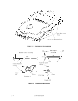
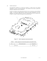
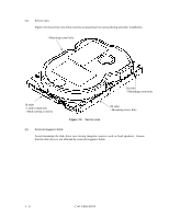
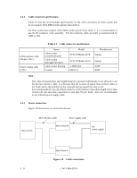
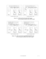
3.3.4 Power supply connector (CN1) Figure 3.9 shows the pin assignment of the power supply connector (CN1). 1 2 3 4 (Viewed from cable side) 1 +12VDC 2 +12V RETURN 3 +5V RETURN 4 +5VDC Figure 3.9 Power supply connector pins (CN1) 3.3.5 System configuration for Ultra DMA Host system that support Ultra DMA transfer modes greater than mode 2 shall not share I/O ports. They shall provide separate drivers and separate receivers for each cable. a) The 80-conductor cable assemblies shall be used for systems operating at Ultra DMA modes greater than 2. The 80-coductor cable assemblies may be used in place of 40conductor cable assemblies to improve signal quality for data transfer modes that do not require an 80-conductor cable assembly. And the 80-conductor cable assembly shall meet the following specifications. 1) The assembly utilizes a fine pitch cable to double the number of conductors available to the 40-pin connector. The grounds assigned by the interface are commoned with the additional 40 conductors to provide a ground between each signal line and provide the effect of a common ground plane. 2) The cable assembly may contain up to 3 connectors which shall be uniquely colored as follows. All connectors shall have position 20 blocked. • The System Board Connector shall have a Blue base and Black retainer. Pin 34 (PDIAG-: CBLID-) shall be connected to ground and shall not be wired to the cable assembly. • Connector Device "0" shall have a Black base and Black retainer. • Connector Device "1" shall have a Gray base and Black retainer. Pin 28 (CSEL) shall not be connected to the cable (contact 28 may be removed to meet this requirement). • The cable assembly may be printed with connector identifiers. 3) Typical cable characteristics are shown as follows. • Cable: AWG 30 (pitch: 0.635 mm) • Single Ended impedance: typical 80 Ω • Cable capacitance: typical 57 pF/m 4) The dimensions are shown in Figure 3.10. C141-E069-02EN 3 - 9
-
 1
1 -
2
-
3
-
4
-
5
-
6
-
7
-
8
-
9
-
10
-
11
-
12
-
13
-
14
-
15
-
16
-
17
-
18
-
19
-
20
-
21
-
22
-
23
-
24
-
25
-
26
-
27
-
28
-
29
-
30
-
31
-
32
-
 33
33 -
 34
34 -
 35
35 -
 36
36 -
 37
37 -
 38
38 -
 39
39 -
 40
40 -
 41
41 -
 42
42 -
 43
43 -
44
-
45
-
46
-
47
-
48
-
49
-
50
-
51
-
52
-
53
-
54
-
55
-
56
-
57
-
58
-
59
-
60
-
61
-
62
-
63
-
64
-
65
-
66
-
67
-
68
-
69
-
70
-
71
-
72
-
73
-
74
-
75
-
76
-
77
-
78
-
79
-
80
-
81
-
82
-
83
-
84
-
85
-
86
-
87
-
88
-
89
-
90
-
91
-
92
-
93
-
94
-
95
-
96
-
97
-
98
-
99
-
100
-
101
-
102
-
103
-
104
-
105
-
106
-
107
-
108
-
109
-
110
-
111
-
112
-
113
-
114
-
115
-
116
-
117
-
118
-
119
-
120
-
121
-
122
-
123
-
124
-
125
-
126
-
127
-
128
-
129
-
130
-
131
-
132
-
133
-
134
-
135
-
136
-
137
-
138
-
139
-
140
-
141
-
142
-
143
-
144
-
145
-
146
-
147
-
148
-
149
-
150
-
151
-
152
-
153
-
154
-
155
-
156
-
157
-
158
-
159
-
160
-
161
-
162
-
163
-
164
-
165
-
166
-
167
-
168
-
169
-
170
-
171
-
172
-
173
-
174
-
175
-
176
-
177
-
178
-
179
-
180
-
181
-
182
-
183
-
184
-
185
-
186
-
187
-
188
-
189
-
190
-
191
 |
 |
