Fujitsu MPD3173AT Product Manual - Page 43
Jumper setting of Cable Select, Example 1 of Cable Select,
 |
View all Fujitsu MPD3173AT manuals
Add to My Manuals
Save this manual to your list of manuals |
Page 43 highlights
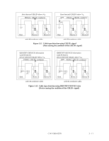
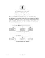
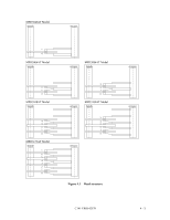
2 468 1 3579 CSEL connected to the interface cable selection can be done by the special interface cable. Figure 3.16 Jumper setting of Cable Select Figures 3.17 and 3.18 show examples of cable selection using unique interface cables. By connecting the CSEL of the master device to the CSEL Line (conductor) of the cable and connecting it to ground further, the CSEL is set to low level. The device is identified as a master device. At this time, the CSEL of the slave device does not have a conductor. Thus, since the slave device is not connected to the CSEL conductor, the CSEL is set to high level. The device is identified as a slave device. CSEL conductor GND Host system Master device Open Slave device Figure 3.17 Example (1) of Cable Select CSEL conductor GND Host system Open Slave device Master device Figure 3.18 Example (2) of Cable Select 3 - 14 C141-E069-02EN
-
 1
1 -
2
-
3
-
4
-
5
-
6
-
7
-
8
-
9
-
10
-
11
-
12
-
13
-
14
-
15
-
16
-
17
-
18
-
19
-
20
-
21
-
22
-
23
-
24
-
25
-
26
-
27
-
28
-
29
-
30
-
31
-
32
-
33
-
34
-
35
-
36
-
37
-
 38
38 -
 39
39 -
 40
40 -
 41
41 -
 42
42 -
 43
43 -
 44
44 -
 45
45 -
 46
46 -
 47
47 -
 48
48 -
49
-
50
-
51
-
52
-
53
-
54
-
55
-
56
-
57
-
58
-
59
-
60
-
61
-
62
-
63
-
64
-
65
-
66
-
67
-
68
-
69
-
70
-
71
-
72
-
73
-
74
-
75
-
76
-
77
-
78
-
79
-
80
-
81
-
82
-
83
-
84
-
85
-
86
-
87
-
88
-
89
-
90
-
91
-
92
-
93
-
94
-
95
-
96
-
97
-
98
-
99
-
100
-
101
-
102
-
103
-
104
-
105
-
106
-
107
-
108
-
109
-
110
-
111
-
112
-
113
-
114
-
115
-
116
-
117
-
118
-
119
-
120
-
121
-
122
-
123
-
124
-
125
-
126
-
127
-
128
-
129
-
130
-
131
-
132
-
133
-
134
-
135
-
136
-
137
-
138
-
139
-
140
-
141
-
142
-
143
-
144
-
145
-
146
-
147
-
148
-
149
-
150
-
151
-
152
-
153
-
154
-
155
-
156
-
157
-
158
-
159
-
160
-
161
-
162
-
163
-
164
-
165
-
166
-
167
-
168
-
169
-
170
-
171
-
172
-
173
-
174
-
175
-
176
-
177
-
178
-
179
-
180
-
181
-
182
-
183
-
184
-
185
-
186
-
187
-
188
-
189
-
190
-
191
 |
 |
