Fujitsu MPD3173AT Product Manual - Page 131
Fujitsu MPD3173AT - Desktop 17.3 GB Hard Drive Manual
 |
View all Fujitsu MPD3173AT manuals
Add to My Manuals
Save this manual to your list of manuals |
Page 131 highlights
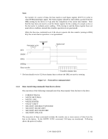
At command issuance (I/O registers setting contents) 1F7H(CM) 1 1 1 1 1 0 0 1 1F6H(DH) × L × DV Max head/LBA [MSB] 1F5H(CH) 1F4H(CL) 1F3H(SN) Max. cylinder [MSB]/Max. LBA Max. cylinder [LSB]/Max. LBA Max. sector/Max. LBA [LSB] 1F2H(SC) xx VV 1F1H(FR) xx At command completion (I/O registers contents to be read) 1F7H(ST) Status information 1F6H(DH) × × × DV Max head/LBA [MSB] 1F5H(CH) 1F4H(CL) 1F3H(SN) Max. cylinder [MSB]/Max. LBA Max. cylinder [LSB]/Max. LBA Max. sector/Max. LBA [LSB] 1F2H(SC) xx 1F1H(ER) Error information (37) READ NATIVE MAX ADDRESS (F8) This command posts the maximum address intrinsic to the device, which can be set by the SET MAX ADDRESS command. Upon receipt of this command, the device sets the BSY bit and indicates the maximum address in the DH, CH, CL and SN registers. Then, it clears BSY and generates an interrupt. At command issuance (I/O registers setting contents) 1F7H(CM) 1 1 1 1 1 0 0 0 1F6H(DH) × L × DV xx 1F5H(CH) xx 1F4H(CL) xx 1F3H(SN) xx 1F2H(SC) xx 1F1H(FR) xx 5 - 64 C141-E069-02EN
-
 1
1 -
2
-
3
-
4
-
5
-
6
-
7
-
8
-
9
-
10
-
11
-
12
-
13
-
14
-
15
-
16
-
17
-
18
-
19
-
20
-
21
-
22
-
23
-
24
-
25
-
26
-
27
-
28
-
29
-
30
-
31
-
32
-
33
-
34
-
35
-
36
-
37
-
38
-
39
-
40
-
41
-
42
-
43
-
44
-
45
-
46
-
47
-
48
-
49
-
50
-
51
-
52
-
53
-
54
-
55
-
56
-
57
-
58
-
59
-
60
-
61
-
62
-
63
-
64
-
65
-
66
-
67
-
68
-
69
-
70
-
71
-
72
-
73
-
74
-
75
-
76
-
77
-
78
-
79
-
80
-
81
-
82
-
83
-
84
-
85
-
86
-
87
-
88
-
89
-
90
-
91
-
92
-
93
-
94
-
95
-
96
-
97
-
98
-
99
-
100
-
101
-
102
-
103
-
104
-
105
-
106
-
107
-
108
-
109
-
110
-
111
-
112
-
113
-
114
-
115
-
116
-
117
-
118
-
119
-
120
-
121
-
122
-
123
-
124
-
125
-
 126
126 -
 127
127 -
 128
128 -
 129
129 -
 130
130 -
 131
131 -
 132
132 -
 133
133 -
 134
134 -
 135
135 -
 136
136 -
137
-
138
-
139
-
140
-
141
-
142
-
143
-
144
-
145
-
146
-
147
-
148
-
149
-
150
-
151
-
152
-
153
-
154
-
155
-
156
-
157
-
158
-
159
-
160
-
161
-
162
-
163
-
164
-
165
-
166
-
167
-
168
-
169
-
170
-
171
-
172
-
173
-
174
-
175
-
176
-
177
-
178
-
179
-
180
-
181
-
182
-
183
-
184
-
185
-
186
-
187
-
188
-
189
-
190
-
191
 |
 |
