Fujitsu MPD3173AT Product Manual - Page 9

Theory Of Device Operation, Interface

Page 9 highlights

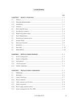
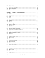
3.4 3.4.1 3.4.2 3.4.3 Jumper Settings ...3 - 12 Location of setting jumpers 3 - 12 Factory default setting ...3 - 13 Jumper configuration...3 - 13 CHAPTER 4 THEORY OF DEVICE OPERATION 4 - 1 4.1 Outline...4 - 1 4.2 Subassemblies ...4 - 1 4.2.1 Disk ...4 - 1 4.2.2 Head ...4 - 2 4.2.3 Spindle...4 - 4 4.2.4 Actuator...4 - 4 4.2.5 Air filter...4 - 4 4.3 Circuit Configuration...4 - 5 4.4 Power-on Sequence ...4 - 7 4.5 Self-calibration ...4 - 9 4.5.1 Self-calibration contents 4 - 9 4.5.2 Execution timing of self-calibration 4 - 10 4.5.3 Command processing during self-calibration 4 - 10 4.6 Read/write Circuit...4 - 11 4.6.1 Read/write preamplifier (PreAMP 4 - 11 4.6.2 Write circuit...4 - 11 4.6.3 Read circuit...4 - 13 4.6.4 Time base generator circuit 4 - 14 4.7 Servo Control ...4 - 14 4.7.1 Servo control circuit ...4 - 15 4.7.2 Data-surface servo format 4 - 18 4.7.3 Servo frame format...4 - 18 4.7.4 Actuator motor control 4 - 20 4.7.5 Spindle motor control...4 - 21 CHAPTER 5 INTERFACE 5 - 1 5.1 Physical Interface ...5 - 2 5.1.1 Interface signals...5 - 2 5.1.2 Signal assignment on the connector 5 - 3 5.2 Logical Interface...5 - 6 viii C141-E069-02EN

  • 1
  • 2
  • 3
  • 4
  • 5
  • 6
  • 7
  • 8
  • 9
  • 10
  • 11
  • 12
  • 13
  • 14
  • 15
  • 16
  • 17
  • 18
  • 19
  • 20
  • 21
  • 22
  • 23
  • 24
  • 25
  • 26
  • 27
  • 28
  • 29
  • 30
  • 31
  • 32
  • 33
  • 34
  • 35
  • 36
  • 37
  • 38
  • 39
  • 40
  • 41
  • 42
  • 43
  • 44
  • 45
  • 46
  • 47
  • 48
  • 49
  • 50
  • 51
  • 52
  • 53
  • 54
  • 55
  • 56
  • 57
  • 58
  • 59
  • 60
  • 61
  • 62
  • 63
  • 64
  • 65
  • 66
  • 67
  • 68
  • 69
  • 70
  • 71
  • 72
  • 73
  • 74
  • 75
  • 76
  • 77
  • 78
  • 79
  • 80
  • 81
  • 82
  • 83
  • 84
  • 85
  • 86
  • 87
  • 88
  • 89
  • 90
  • 91
  • 92
  • 93
  • 94
  • 95
  • 96
  • 97
  • 98
  • 99
  • 100
  • 101
  • 102
  • 103
  • 104
  • 105
  • 106
  • 107
  • 108
  • 109
  • 110
  • 111
  • 112
  • 113
  • 114
  • 115
  • 116
  • 117
  • 118
  • 119
  • 120
  • 121
  • 122
  • 123
  • 124
  • 125
  • 126
  • 127
  • 128
  • 129
  • 130
  • 131
  • 132
  • 133
  • 134
  • 135
  • 136
  • 137
  • 138
  • 139
  • 140
  • 141
  • 142
  • 143
  • 144
  • 145
  • 146
  • 147
  • 148
  • 149
  • 150
  • 151
  • 152
  • 153
  • 154
  • 155
  • 156
  • 157
  • 158
  • 159
  • 160
  • 161
  • 162
  • 163
  • 164
  • 165
  • 166
  • 167
  • 168
  • 169
  • 170
  • 171
  • 172
  • 173
  • 174
  • 175
  • 176
  • 177
  • 178
  • 179
  • 180
  • 181
  • 182
  • 183
  • 184
  • 185
  • 186
  • 187
  • 188
  • 189
  • 190
  • 191

C141-E069-02EN
viii
3.4
Jumper Settings
..............................................................................................................
3 - 12
3.4.1
Location of setting jumpers
............................................................................................
3 - 12
3.4.2
Factory default setting
....................................................................................................
3 - 13
3.4.3
Jumper configuration
......................................................................................................
3 - 13
CHAPTER 4
THEORY OF DEVICE OPERATION
.........................................................
4 - 1
4.1
Outline
............................................................................................................................
4 - 1
4.2
Subassemblies
................................................................................................................
4 - 1
4.2.1
Disk
................................................................................................................................
4 - 1
4.2.2
Head
...............................................................................................................................
4 - 2
4.2.3
Spindle
............................................................................................................................
4 - 4
4.2.4
Actuator
..........................................................................................................................
4 - 4
4.2.5
Air filter
..........................................................................................................................
4 - 4
4.3
Circuit Configuration
......................................................................................................
4 - 5
4.4
Power-on Sequence
........................................................................................................
4 - 7
4.5
Self-calibration
...............................................................................................................
4 - 9
4.5.1
Self-calibration contents
.................................................................................................
4 - 9
4.5.2
Execution timing of self-calibration
...............................................................................
4 - 10
4.5.3
Command processing during self-calibration
.................................................................
4 - 10
4.6
Read/write Circuit
...........................................................................................................
4 - 11
4.6.1
Read/write preamplifier (PreAMP)
.................................................................................
4 - 11
4.6.2
Write circuit
....................................................................................................................
4 - 11
4.6.3
Read circuit
.....................................................................................................................
4 - 13
4.6.4
Time base generator circuit
.............................................................................................
4 - 14
4.7
Servo Control
.................................................................................................................
4 - 14
4.7.1
Servo control circuit
.......................................................................................................
4 - 15
4.7.2
Data-surface servo format
...............................................................................................
4 - 18
4.7.3
Servo frame format
.........................................................................................................
4 - 18
4.7.4
Actuator motor control
...................................................................................................
4 - 20
4.7.5
Spindle motor control
.....................................................................................................
4 - 21
CHAPTER 5
INTERFACE
...................................................................................................
5 - 1
5.1
Physical Interface
...........................................................................................................
5 - 2
5.1.1
Interface signals
..............................................................................................................
5 - 2
5.1.2
Signal assignment on the connector
...............................................................................
5 - 3
5.2
Logical Interface
.............................................................................................................
5 - 6