Fujitsu MPD3173AT Product Manual - Page 37
Cable connector specifications, Table 3.2, Device connection, Cable connections
 |
View all Fujitsu MPD3173AT manuals
Add to My Manuals
Save this manual to your list of manuals |
Page 37 highlights
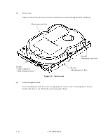
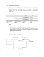
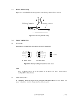
3.3.2 Cable connector specifications Table 3.2 lists the recommended specifications for the cable connectors for Host system that do not support Ultra DMA modes greater than mode 2. For Host system that support Ultra DMA modes greater than mode 2, it is recommended to use the 80-conductor cable assembly. The 80-conductor cable assembly is manufactured by AMP or 3M. ATA interface cable (40-pin, CN1) Power supply cable (CN1) Table 3.2 Cable connector specifications Name Cable socket (closed-end type) Cable socket (through-end type) Cable socket housing Contact Model FCN-707B040-AU/B FCN-707B040-AU/O 1-480424-0 60617-4 Manufacturer Fujitsu Fujitsu AMP AMP Note : The cable of twisted pairs and neighboring line separated individually is not allowed to use for the host interface cable. It is because that the location of signal lines in these cables is not fixed, and so the problem on the crosstalk among signal lines may occur. It is recommended to use the ribbon cable for ATA interface that cable length is less than 18 inch (46 cm) and cable capacitance is less than 35 pico farad. Also it is recommended to use AWG18 power supply cable. 3.3.3 Device connection Figure 3.8 shows how to connect the devices. ATA interface cable Power supply cable Host system Disk Drive #0 DC power supply Disk Drive #1 Figure 3.8 Cable connections 3 - 8 C141-E069-02EN
-
 1
1 -
2
-
3
-
4
-
5
-
6
-
7
-
8
-
9
-
10
-
11
-
12
-
13
-
14
-
15
-
16
-
17
-
18
-
19
-
20
-
21
-
22
-
23
-
24
-
25
-
26
-
27
-
28
-
29
-
30
-
31
-
 32
32 -
 33
33 -
 34
34 -
 35
35 -
 36
36 -
 37
37 -
 38
38 -
 39
39 -
 40
40 -
 41
41 -
 42
42 -
43
-
44
-
45
-
46
-
47
-
48
-
49
-
50
-
51
-
52
-
53
-
54
-
55
-
56
-
57
-
58
-
59
-
60
-
61
-
62
-
63
-
64
-
65
-
66
-
67
-
68
-
69
-
70
-
71
-
72
-
73
-
74
-
75
-
76
-
77
-
78
-
79
-
80
-
81
-
82
-
83
-
84
-
85
-
86
-
87
-
88
-
89
-
90
-
91
-
92
-
93
-
94
-
95
-
96
-
97
-
98
-
99
-
100
-
101
-
102
-
103
-
104
-
105
-
106
-
107
-
108
-
109
-
110
-
111
-
112
-
113
-
114
-
115
-
116
-
117
-
118
-
119
-
120
-
121
-
122
-
123
-
124
-
125
-
126
-
127
-
128
-
129
-
130
-
131
-
132
-
133
-
134
-
135
-
136
-
137
-
138
-
139
-
140
-
141
-
142
-
143
-
144
-
145
-
146
-
147
-
148
-
149
-
150
-
151
-
152
-
153
-
154
-
155
-
156
-
157
-
158
-
159
-
160
-
161
-
162
-
163
-
164
-
165
-
166
-
167
-
168
-
169
-
170
-
171
-
172
-
173
-
174
-
175
-
176
-
177
-
178
-
179
-
180
-
181
-
182
-
183
-
184
-
185
-
186
-
187
-
188
-
189
-
190
-
191
 |
 |
