Fujitsu MPD3173AT Product Manual - Page 14
Tables
 |
View all Fujitsu MPD3173AT manuals
Add to My Manuals
Save this manual to your list of manuals |
Page 14 highlights
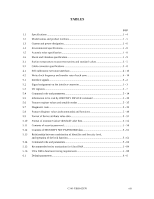
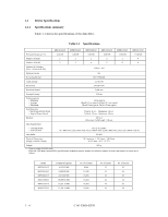
TABLES page 1.1 Specifications ...1 - 4 1.2 Model names and product numbers 1 - 5 1.3 Current and power dissipation 1 - 6 1.4 Environmental specifications 1 - 8 1.5 Acoustic noise specification 1 - 8 1.6 Shock and vibration specification 1 - 9 3.1 Surface temperature measurement points and standard values 3 - 5 3.2 Cable connector specifications 3 - 8 4.1 Self-calibration execution timechart 4 - 10 4.2 Write clock frequency and transfer rate of each zone 4 - 14 5.1 Interface signals...5 - 2 5.2 Signal assignment on the interface connector 5 - 3 5.3 I/O registers ...5 - 7 5.4 Command code and parameters 5 - 14 5.5 Information to be read by IDENTIFY DEVICE command 5 - 30 5.6 Features register values and settable modes 5 - 35 5.7 Diagnostic code ...5 - 39 5.8 Features Register values (subcommands) and functions 5 - 49 5.9 Format of device attribute value data 5 - 51 5.10 Format of insurance failure threshold value data 5 - 52 5.11 Contents of security password 5 - 56 5.12 Contents of SECURITY SET PASSWORD data 5 - 61 5.13 Relationship between combination of Identifier and Security level, and operation of the lock function 5 - 61 5.14 Command code and parameters 5 - 66 5.15 Recommended series termination for Ultra DMA 5 - 84 5.16 Ultra DMA data burst timing requirements 5 - 88 6.1 Default parameters...6 - 6 C141-E069-02EN xiii
-
 1
1 -
2
-
3
-
4
-
5
-
6
-
7
-
8
-
 9
9 -
 10
10 -
 11
11 -
 12
12 -
 13
13 -
 14
14 -
 15
15 -
 16
16 -
 17
17 -
 18
18 -
 19
19 -
20
-
21
-
22
-
23
-
24
-
25
-
26
-
27
-
28
-
29
-
30
-
31
-
32
-
33
-
34
-
35
-
36
-
37
-
38
-
39
-
40
-
41
-
42
-
43
-
44
-
45
-
46
-
47
-
48
-
49
-
50
-
51
-
52
-
53
-
54
-
55
-
56
-
57
-
58
-
59
-
60
-
61
-
62
-
63
-
64
-
65
-
66
-
67
-
68
-
69
-
70
-
71
-
72
-
73
-
74
-
75
-
76
-
77
-
78
-
79
-
80
-
81
-
82
-
83
-
84
-
85
-
86
-
87
-
88
-
89
-
90
-
91
-
92
-
93
-
94
-
95
-
96
-
97
-
98
-
99
-
100
-
101
-
102
-
103
-
104
-
105
-
106
-
107
-
108
-
109
-
110
-
111
-
112
-
113
-
114
-
115
-
116
-
117
-
118
-
119
-
120
-
121
-
122
-
123
-
124
-
125
-
126
-
127
-
128
-
129
-
130
-
131
-
132
-
133
-
134
-
135
-
136
-
137
-
138
-
139
-
140
-
141
-
142
-
143
-
144
-
145
-
146
-
147
-
148
-
149
-
150
-
151
-
152
-
153
-
154
-
155
-
156
-
157
-
158
-
159
-
160
-
161
-
162
-
163
-
164
-
165
-
166
-
167
-
168
-
169
-
170
-
171
-
172
-
173
-
174
-
175
-
176
-
177
-
178
-
179
-
180
-
181
-
182
-
183
-
184
-
185
-
186
-
187
-
188
-
189
-
190
-
191
 |
 |