Fujitsu MPD3173AT Product Manual - Page 151
: A.I. means an Active Inductance.
 |
View all Fujitsu MPD3173AT manuals
Add to My Manuals
Save this manual to your list of manuals |
Page 151 highlights
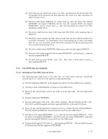
I) The CRC generator polynomial is : G (X) = X16 + X12 + X5 + 1. Note: Since no bit clock is available, the recommended approach for calculating CRC is to use a word clock derived from the bus strobe. The combinational logic shall then be equivalent to shifting sixteen bits serially through the generator polynominal where DD0 is shifted in first and DD15 is shifted in last. 5.5.6 Series termination required for Ultra DMA Series termination resistors are required at both the host and the device for operation in any of the Ultra DMA Modes. The following table describes recommended values for series termination at the host and the device. Table 5.15 Recommended series termination for Ultra DMA Signal DIOR-:HDMARDY-:HSTROBE Host Termination 33 ohm Device Termination 120 ohm A.I.*1 DIOW-:STOP 33 ohm 82 ohm CS0-, CS1- 33 ohm 82 ohm DA0, DA1, DA2 33 ohm 82 ohm DMACKDD15 through DD0 33 ohm 33 ohm 82 ohm 120 ohm A.I.*1 DMARQ 82 ohm 22 ohm INTRQ 82 ohm 22 ohm IORDY:DDMARDY-:DSTROBE 82 ohm 22 ohm Note: Only those signals requiring termination are listed in this table. If a signal is not listed, series termination is not required for operation in an Ultra DMA Mode. For signals also requiring a pull-up or pull-down resistor at the host see Figure 5.7. *1: "A.I." means an Active Inductance. Figure 5.7 Ultra DMA termination with pull-up or pull-down 5 - 84 C141-E069-02EN
-
 1
1 -
2
-
3
-
4
-
5
-
6
-
7
-
8
-
9
-
10
-
11
-
12
-
13
-
14
-
15
-
16
-
17
-
18
-
19
-
20
-
21
-
22
-
23
-
24
-
25
-
26
-
27
-
28
-
29
-
30
-
31
-
32
-
33
-
34
-
35
-
36
-
37
-
38
-
39
-
40
-
41
-
42
-
43
-
44
-
45
-
46
-
47
-
48
-
49
-
50
-
51
-
52
-
53
-
54
-
55
-
56
-
57
-
58
-
59
-
60
-
61
-
62
-
63
-
64
-
65
-
66
-
67
-
68
-
69
-
70
-
71
-
72
-
73
-
74
-
75
-
76
-
77
-
78
-
79
-
80
-
81
-
82
-
83
-
84
-
85
-
86
-
87
-
88
-
89
-
90
-
91
-
92
-
93
-
94
-
95
-
96
-
97
-
98
-
99
-
100
-
101
-
102
-
103
-
104
-
105
-
106
-
107
-
108
-
109
-
110
-
111
-
112
-
113
-
114
-
115
-
116
-
117
-
118
-
119
-
120
-
121
-
122
-
123
-
124
-
125
-
126
-
127
-
128
-
129
-
130
-
131
-
132
-
133
-
134
-
135
-
136
-
137
-
138
-
139
-
140
-
141
-
142
-
143
-
144
-
145
-
 146
146 -
 147
147 -
 148
148 -
 149
149 -
 150
150 -
 151
151 -
 152
152 -
 153
153 -
 154
154 -
 155
155 -
 156
156 -
157
-
158
-
159
-
160
-
161
-
162
-
163
-
164
-
165
-
166
-
167
-
168
-
169
-
170
-
171
-
172
-
173
-
174
-
175
-
176
-
177
-
178
-
179
-
180
-
181
-
182
-
183
-
184
-
185
-
186
-
187
-
188
-
189
-
190
-
191
 |
 |
