Fujitsu MPD3173AT Product Manual - Page 83
Command descriptions
 |
View all Fujitsu MPD3173AT manuals
Add to My Manuals
Save this manual to your list of manuals |
Page 83 highlights
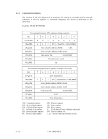
5.3.2 Command descriptions The contents of the I/O registers to be necessary for issuing a command and the example indication of the I/O registers at command completion are shown as following in this subsection. Example: READ SECTOR(S) At command issuance (I/O registers setting contents) Bit 76543210 1F7H(CM) 1F6H(DH) 00100000 × L × DV Head No. / LBA [MSB] 1F5H(CH) 1F4H(CL) Start cylinder address [MSB] / LBA Start cylinder address [LSB] / LBA 1F3H(SN) Start sector No. / LBA [LSB] 1F2H(SC) Transfer sector count 1F1H(FR) xx At command completion (I/O registers contents to be read) Bit 76543210 1F7H(ST) 1F6H(DH) Error information × L × DV End Head No. / LBA [MSB] 1F5H(CH) 1F4H(CL) End cylinder address [MSB] / LBA End cylinder address [LSB] / LBA 1F3H(SN) End sector No. / LBA [LSB] 1F2H(SC) X'00' 1F1H(ER) Error information CM: Command register DH: Device/Head register CH: Cylinder High register CL: Cylinder Low register SN: Sector Number register SC: Sector Count register FR: Features register ST: Status register ER: Error register L: LBA (logical block address) setting bit DV: Device address. bit x, xx: Do not care (no necessary to set) 5 - 16 C141-E069-02EN
-
 1
1 -
2
-
3
-
4
-
5
-
6
-
7
-
8
-
9
-
10
-
11
-
12
-
13
-
14
-
15
-
16
-
17
-
18
-
19
-
20
-
21
-
22
-
23
-
24
-
25
-
26
-
27
-
28
-
29
-
30
-
31
-
32
-
33
-
34
-
35
-
36
-
37
-
38
-
39
-
40
-
41
-
42
-
43
-
44
-
45
-
46
-
47
-
48
-
49
-
50
-
51
-
52
-
53
-
54
-
55
-
56
-
57
-
58
-
59
-
60
-
61
-
62
-
63
-
64
-
65
-
66
-
67
-
68
-
69
-
70
-
71
-
72
-
73
-
74
-
75
-
76
-
77
-
 78
78 -
 79
79 -
 80
80 -
 81
81 -
 82
82 -
 83
83 -
 84
84 -
 85
85 -
 86
86 -
 87
87 -
 88
88 -
89
-
90
-
91
-
92
-
93
-
94
-
95
-
96
-
97
-
98
-
99
-
100
-
101
-
102
-
103
-
104
-
105
-
106
-
107
-
108
-
109
-
110
-
111
-
112
-
113
-
114
-
115
-
116
-
117
-
118
-
119
-
120
-
121
-
122
-
123
-
124
-
125
-
126
-
127
-
128
-
129
-
130
-
131
-
132
-
133
-
134
-
135
-
136
-
137
-
138
-
139
-
140
-
141
-
142
-
143
-
144
-
145
-
146
-
147
-
148
-
149
-
150
-
151
-
152
-
153
-
154
-
155
-
156
-
157
-
158
-
159
-
160
-
161
-
162
-
163
-
164
-
165
-
166
-
167
-
168
-
169
-
170
-
171
-
172
-
173
-
174
-
175
-
176
-
177
-
178
-
179
-
180
-
181
-
182
-
183
-
184
-
185
-
186
-
187
-
188
-
189
-
190
-
191
 |
 |
