Fujitsu MPD3173AT Product Manual - Page 98
MPD3043AT, MPD3064AT, MPD3084AT, MPD3108AT, MPD3130AT, MPD3173AT
 |
View all Fujitsu MPD3173AT manuals
Add to My Manuals
Save this manual to your list of manuals |
Page 98 highlights
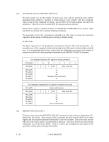
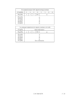
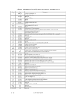
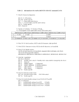
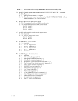
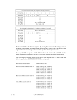
Table 5.5 Information to be read by IDENTIFY DEVICE command (2 of 4) *1 Word 0: General configuration Bit 15: 0 = ATA device 0 Bit 14-8: Vendor specific 0 Bit 7: 1 = Removable media device 0 Bit 6: 1 = not removable controller and/or device 1 Bit 5-1: Vendor specific 0 Bit 0: Reserved 0 *2 Number of Cylinders, *3 Number of Heads, *11 Total number of user addressable sectors (LBA mode only.) MPD3043AT MPD3064AT MPD3084AT MPD3108AT MPD3130AT MPD3173AT *2 X'22EC' X'3462' X'3FFF' *3 X'000F' X'0010' *11 X'0080E92C' X'00C15DC2' X'00FBFC10' X'0141E400' X'01840F20' X'203A4D0' *4 Word 10-19: Serial number; ASCII code (20 characters, right-justified) *5 Word 23-26: Firmware revision; ASCII code (8 characters, Left-justified) *6 Word 27-46: Model number; ASCII code (40 characters, Left-justified), remainder filled with blank code (X'20') One of the following model numbers; MPD3043AT, MPD3064AT, MPD3084AT, MPD3108AT, MPD3130AT, MPD3173AT *7 Word 49: Capabilities Bit 15-14: Reserved Bit 13: Standby timer value 0 = Standby timer values shall be managed by the device Bit 12: Reserved Bit 11: IORDY support 1=Supported Bit 10: IORDY inhibition 0=Disable inhibition Bit 9: LBA support 1=Supported Bit 8: DMA support 1=Supported Bit 7-0: Vendor specific *8 Word 51: PIO data transfer mode Bit 15-8: PIO data transfer mode Bit 7-0: Vendor specific X'02'=PIO mode 2 *9 Word 53: Enable/disable setting of word 54-58 ,64-70 and 88 Bit 15-3: Reserved Bit 2: Enable/disable setting of word 88 1=Enable Bit 1: Enable/disable setting of word 64-70 1=Enable Bit 0: Enable/disable setting of word 54-58 1=Enable C141-E069-02EN 5 - 31
-
 1
1 -
2
-
3
-
4
-
5
-
6
-
7
-
8
-
9
-
10
-
11
-
12
-
13
-
14
-
15
-
16
-
17
-
18
-
19
-
20
-
21
-
22
-
23
-
24
-
25
-
26
-
27
-
28
-
29
-
30
-
31
-
32
-
33
-
34
-
35
-
36
-
37
-
38
-
39
-
40
-
41
-
42
-
43
-
44
-
45
-
46
-
47
-
48
-
49
-
50
-
51
-
52
-
53
-
54
-
55
-
56
-
57
-
58
-
59
-
60
-
61
-
62
-
63
-
64
-
65
-
66
-
67
-
68
-
69
-
70
-
71
-
72
-
73
-
74
-
75
-
76
-
77
-
78
-
79
-
80
-
81
-
82
-
83
-
84
-
85
-
86
-
87
-
88
-
89
-
90
-
91
-
92
-
 93
93 -
 94
94 -
 95
95 -
 96
96 -
 97
97 -
 98
98 -
 99
99 -
 100
100 -
 101
101 -
 102
102 -
 103
103 -
104
-
105
-
106
-
107
-
108
-
109
-
110
-
111
-
112
-
113
-
114
-
115
-
116
-
117
-
118
-
119
-
120
-
121
-
122
-
123
-
124
-
125
-
126
-
127
-
128
-
129
-
130
-
131
-
132
-
133
-
134
-
135
-
136
-
137
-
138
-
139
-
140
-
141
-
142
-
143
-
144
-
145
-
146
-
147
-
148
-
149
-
150
-
151
-
152
-
153
-
154
-
155
-
156
-
157
-
158
-
159
-
160
-
161
-
162
-
163
-
164
-
165
-
166
-
167
-
168
-
169
-
170
-
171
-
172
-
173
-
174
-
175
-
176
-
177
-
178
-
179
-
180
-
181
-
182
-
183
-
184
-
185
-
186
-
187
-
188
-
189
-
190
-
191
 |
 |