Fujitsu MPD3173AT Product Manual - Page 80
Control block registers, Host Commands
 |
View all Fujitsu MPD3173AT manuals
Add to My Manuals
Save this manual to your list of manuals |
Page 80 highlights
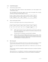
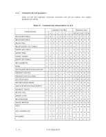
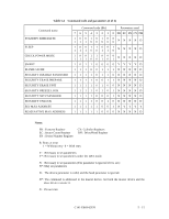
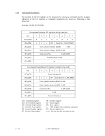
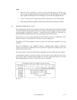
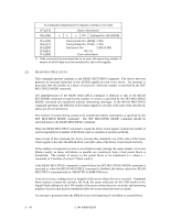
5.2.3 Control block registers (1) Alternate Status register (X'3F6') The Alternate Status register contains the same information as the Status register of the command block register. The only difference from the Status register is that a read of this register does not imply Interrupt Acknowledge and INTRQ signal is not reset. Bit 7 BSY Bit 6 DRDY Bit 5 DF Bit 4 DSC Bit 3 DRQ Bit 2 0 Bit 1 0 Bit 0 ERR (2) Device Control register (X'3F6') The Device Control register contains device interrupt and software reset. Bit 7 X Bit 6 X Bit 5 X Bit 4 X Bit 3 X Bit 2 SRST Bit 1 nIEN Bit 0 0 - Bit 2: - Bit 1: SRST is the host software reset bit. When this bit is set, the device is held reset state. When two device are daisy chained on the interface, setting this bit resets both device simultaneously. The slave device is not required to execute the DASP- handshake. nIEN bit enables an interrupt (INTRQ signal) from the device to the host. When this bit is 0 and the device is selected, an interruption (INTRQ signal) can be enabled through a tri-state buffer. When this bit is 1 or the device is not selected, the INTRQ signal is in the high-impedance state. 5.3 Host Commands The host system issues a command to the device by writing necessary parameters in related registers in the command block and writing a command code in the Command register. The device can accept the command when the BSY bit is 0 (the device is not in the busy status). The host system can halt the uncompleted command execution only at execution of hardware or software reset. When the BSY bit is 1 or the DRQ bit is 1 (the device is requesting the data transfer) and the host system writes to the command register, the correct device operation is not guaranteed. C141-E069-02EN 5 - 13
-
 1
1 -
2
-
3
-
4
-
5
-
6
-
7
-
8
-
9
-
10
-
11
-
12
-
13
-
14
-
15
-
16
-
17
-
18
-
19
-
20
-
21
-
22
-
23
-
24
-
25
-
26
-
27
-
28
-
29
-
30
-
31
-
32
-
33
-
34
-
35
-
36
-
37
-
38
-
39
-
40
-
41
-
42
-
43
-
44
-
45
-
46
-
47
-
48
-
49
-
50
-
51
-
52
-
53
-
54
-
55
-
56
-
57
-
58
-
59
-
60
-
61
-
62
-
63
-
64
-
65
-
66
-
67
-
68
-
69
-
70
-
71
-
72
-
73
-
74
-
 75
75 -
 76
76 -
 77
77 -
 78
78 -
 79
79 -
 80
80 -
 81
81 -
 82
82 -
 83
83 -
 84
84 -
 85
85 -
86
-
87
-
88
-
89
-
90
-
91
-
92
-
93
-
94
-
95
-
96
-
97
-
98
-
99
-
100
-
101
-
102
-
103
-
104
-
105
-
106
-
107
-
108
-
109
-
110
-
111
-
112
-
113
-
114
-
115
-
116
-
117
-
118
-
119
-
120
-
121
-
122
-
123
-
124
-
125
-
126
-
127
-
128
-
129
-
130
-
131
-
132
-
133
-
134
-
135
-
136
-
137
-
138
-
139
-
140
-
141
-
142
-
143
-
144
-
145
-
146
-
147
-
148
-
149
-
150
-
151
-
152
-
153
-
154
-
155
-
156
-
157
-
158
-
159
-
160
-
161
-
162
-
163
-
164
-
165
-
166
-
167
-
168
-
169
-
170
-
171
-
172
-
173
-
174
-
175
-
176
-
177
-
178
-
179
-
180
-
181
-
182
-
183
-
184
-
185
-
186
-
187
-
188
-
189
-
190
-
191
 |
 |
