Fujitsu MPD3173AT Product Manual - Page 39
Cable configuration
 |
View all Fujitsu MPD3173AT manuals
Add to My Manuals
Save this manual to your list of manuals |
Page 39 highlights
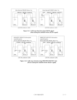
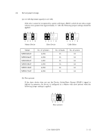
Pin 40 (Ground) Pin 34 Pin 30 (Ground) Pin 26 (Ground) Pin 24 (Ground) Pin 22 (Ground) Pin 19 (Ground) Pin 2 (Ground) 254.0 to 457.2 mm (10 to 18 inch) 127.0 to 304.8 mm 101.6 to 152.4 mm (5 to 12 inch) (4 to 6 inch) open Symbolizes Pin 34 Conductor being cut Position 1 Pin 34 contact (PDIAG-:CBLID- signal) System Board Connector Connector 1 Figure 3.10 Cable configuration Connector 2 b) Host system that do not support Ultra DMA modes greater than mode 2 shall not connect to the PDIAG-:CBLID- signal. c) Host system that do support Ultra DMA modes greater than mode 2 shall either connect directly to the device without using a cable assembly, or determine the cable assembly type. Determining the cable assembly type may be done either by the host sensing the condition of the PDIAG-:CBLID- signal (see Figure 3.11), or by relying on information from the device (see Figure 3.12). Hosts that rely on information from the device shall have a 0.047 µF capacitor connected from the PDIAG-:CBLID- signal to ground. The tolerance on this capacitor shall be 20% or less. 3 - 10 C141-E069-02EN
-
 1
1 -
2
-
3
-
4
-
5
-
6
-
7
-
8
-
9
-
10
-
11
-
12
-
13
-
14
-
15
-
16
-
17
-
18
-
19
-
20
-
21
-
22
-
23
-
24
-
25
-
26
-
27
-
28
-
29
-
30
-
31
-
32
-
33
-
 34
34 -
 35
35 -
 36
36 -
 37
37 -
 38
38 -
 39
39 -
 40
40 -
 41
41 -
 42
42 -
 43
43 -
 44
44 -
45
-
46
-
47
-
48
-
49
-
50
-
51
-
52
-
53
-
54
-
55
-
56
-
57
-
58
-
59
-
60
-
61
-
62
-
63
-
64
-
65
-
66
-
67
-
68
-
69
-
70
-
71
-
72
-
73
-
74
-
75
-
76
-
77
-
78
-
79
-
80
-
81
-
82
-
83
-
84
-
85
-
86
-
87
-
88
-
89
-
90
-
91
-
92
-
93
-
94
-
95
-
96
-
97
-
98
-
99
-
100
-
101
-
102
-
103
-
104
-
105
-
106
-
107
-
108
-
109
-
110
-
111
-
112
-
113
-
114
-
115
-
116
-
117
-
118
-
119
-
120
-
121
-
122
-
123
-
124
-
125
-
126
-
127
-
128
-
129
-
130
-
131
-
132
-
133
-
134
-
135
-
136
-
137
-
138
-
139
-
140
-
141
-
142
-
143
-
144
-
145
-
146
-
147
-
148
-
149
-
150
-
151
-
152
-
153
-
154
-
155
-
156
-
157
-
158
-
159
-
160
-
161
-
162
-
163
-
164
-
165
-
166
-
167
-
168
-
169
-
170
-
171
-
172
-
173
-
174
-
175
-
176
-
177
-
178
-
179
-
180
-
181
-
182
-
183
-
184
-
185
-
186
-
187
-
188
-
189
-
190
-
191
 |
 |
