HP 6125XLG R2306-HP 6125XLG Blade Switch ACL and QoS Configuration Guide - Page 74
Nesting configuration example, Network requirements, Configuration procedure, Configuring PE 1
 |
View all HP 6125XLG manuals
Add to My Manuals
Save this manual to your list of manuals |
Page 74 highlights
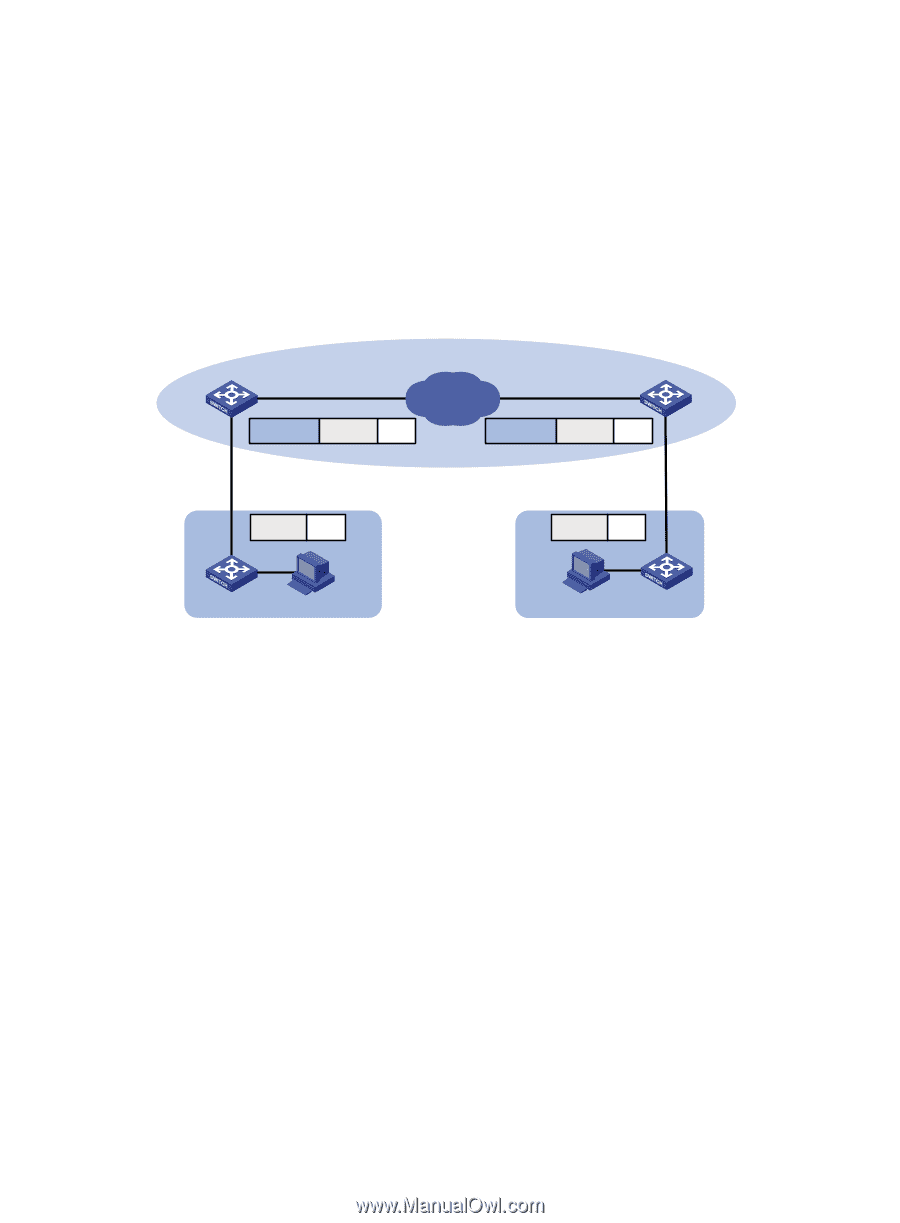
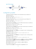
Nesting configuration example Network requirements As shown in Figure 19, Site 1 and Site 2 in VPN A are two branches of a company, and they use VLAN 5 to transmit traffic. Because Site 1 and Site 2 are located in different areas, the two sites use the VPN access service of a service provider. The service provider assigns VLAN 100 to the two sites. Configure nesting, so that the two branches can communicate through the service provider network. Figure 19 Network diagram PE 1 XGE1/1/5 Public network XGE1/1/6 IP network XGE1/1/6 PE 2 VLAN 100 VLAN 5 Data VLAN 100 VLAN 5 Data XGE1/1/5 VLAN 5 Data VLAN 5 Data CE 1 VLAN 5 VPN A Site 1 VPN A Site 2 CE 2 Configuration procedure Configuring PE 1 # Create a class named test to match traffic with CVLAN tag 5. system-view [PE1] traffic classifier test [PE1-classifier-test] if-match customer-vlan-id 5 [PE1-classifier-test] quit # Configure an action of add outer VLAN tag 100 in the traffic behavior named test. [PE1] traffic behavior test [PE1-behavior-test] nest top-most vlan 100 [PE1-behavior-test] quit # Create a QoS policy named test, and associate class test with behavior test in the QoS policy. [PE1] qos policy test [PE1-qospolicy-test] classifier test behavior test [PE1-qospolicy-test] quit # Configure the downlink port Ten-GigabitEthernet 1/1/5 as a hybrid port, and assign the port to VLAN 100 as an untagged member. [PE1] interface ten-gigabitethernet 1/1/5 [PE1-Ten-GigabitEthernet1/1/5] port link-type hybrid 68
-
 1
1 -
2
-
3
-
4
-
5
-
6
-
7
-
8
-
9
-
10
-
11
-
12
-
13
-
14
-
15
-
16
-
17
-
18
-
19
-
20
-
21
-
22
-
23
-
24
-
25
-
26
-
27
-
28
-
29
-
30
-
31
-
32
-
33
-
34
-
35
-
36
-
37
-
38
-
39
-
40
-
41
-
42
-
43
-
44
-
45
-
46
-
47
-
48
-
49
-
50
-
51
-
52
-
53
-
54
-
55
-
56
-
57
-
58
-
59
-
60
-
61
-
62
-
63
-
64
-
65
-
66
-
67
-
68
-
 69
69 -
 70
70 -
 71
71 -
 72
72 -
 73
73 -
 74
74 -
 75
75 -
 76
76 -
 77
77 -
 78
78 -
 79
79 -
80
-
81
-
82
-
83
-
84
-
85
-
86
-
87
-
88
-
89
-
90
-
91
-
92
-
93
-
94
-
95
-
96
-
97
-
98
-
99
-
100
-
101
-
102
-
103
-
104
-
105
-
106
-
107
-
108
-
109
 |
 |