HP 6125XLG R2306-HP 6125XLG Blade Switch ACL and QoS Configuration Guide - Page 77
Configuration example, Network requirements
 |
View all HP 6125XLG manuals
Add to My Manuals
Save this manual to your list of manuals |
Page 77 highlights
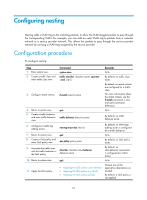
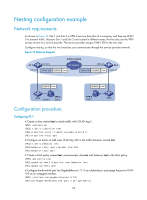
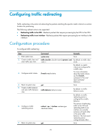
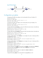
Step 8. Create a QoS policy and enter QoS policy view. Command qos policy policy-name 9. Associate the traffic class with the traffic behavior in classifier classifier-name behavior the QoS policy. behavior-name 10. Return to system view. quit 11. Apply the QoS policy. • Applying the QoS policy to an interface • Applying the QoS policy to a VLAN • Applying the QoS policy globally 12. (Optional.) Display traffic redirecting configuration information. display traffic behavior user-defined [ behavior-name ] Remarks By default, no QoS policy exists. By default, no class-behavior association is configured for a QoS policy. N/A Choose one of the application destinations as needed. By default, a QoS policy is not applied. Available in any view. Configuration example Network requirements As shown in Figure 20: • Device A is connected to Device B through two links. At the same time, Device A and Device B are each connected to other devices. • Ten-GigabitEthernet 1/1/6 of Device A and Ten-GigabitEthernet 1/1/6 of Device B belong to VLAN 200. • Ten-GigabitEthernet 1/1/7 of Device A and Ten-GigabitEthernet 1/1/7 of Device B belong to VLAN 201. • On Device A, the IP address of VLAN-interface 200 is 200.1.1.1/24, and that of VLAN-interface 201 is 201.1.1.1/24. • On Device B, the IP address of VLAN-interface 200 is 200.1.1.2/24, and that of VLAN-interface 201 is 201.1.1.2/24. Configure the actions of redirecting traffic to an interface so that: • Packets with source IP address 2.1.1.1 received on Ten-GigabitEthernet 1/0/1 of Device A are forwarded to Ten-GigabitEthernet 1/0/2. • Packets with source IP address 2.1.1.2 received on Ten-GigabitEthernet 1/0/1 of Device A are forwarded to Ten-GigabitEthernet 1/0/3. • Other packets received on Ten-GigabitEthernet 1/0/1 of Device A are forwarded according to the routing table. 71
-
 1
1 -
2
-
3
-
4
-
5
-
6
-
7
-
8
-
9
-
10
-
11
-
12
-
13
-
14
-
15
-
16
-
17
-
18
-
19
-
20
-
21
-
22
-
23
-
24
-
25
-
26
-
27
-
28
-
29
-
30
-
31
-
32
-
33
-
34
-
35
-
36
-
37
-
38
-
39
-
40
-
41
-
42
-
43
-
44
-
45
-
46
-
47
-
48
-
49
-
50
-
51
-
52
-
53
-
54
-
55
-
56
-
57
-
58
-
59
-
60
-
61
-
62
-
63
-
64
-
65
-
66
-
67
-
68
-
69
-
70
-
71
-
 72
72 -
 73
73 -
 74
74 -
 75
75 -
 76
76 -
 77
77 -
 78
78 -
 79
79 -
 80
80 -
 81
81 -
 82
82 -
83
-
84
-
85
-
86
-
87
-
88
-
89
-
90
-
91
-
92
-
93
-
94
-
95
-
96
-
97
-
98
-
99
-
100
-
101
-
102
-
103
-
104
-
105
-
106
-
107
-
108
-
109
 |
 |
