HP 6125XLG R2306-HP 6125XLG Blade Switch IRF Configuration Guide - Page 19
Setup and configuration task list
 |
View all HP 6125XLG manuals
Add to My Manuals
Save this manual to your list of manuals |
Page 19 highlights
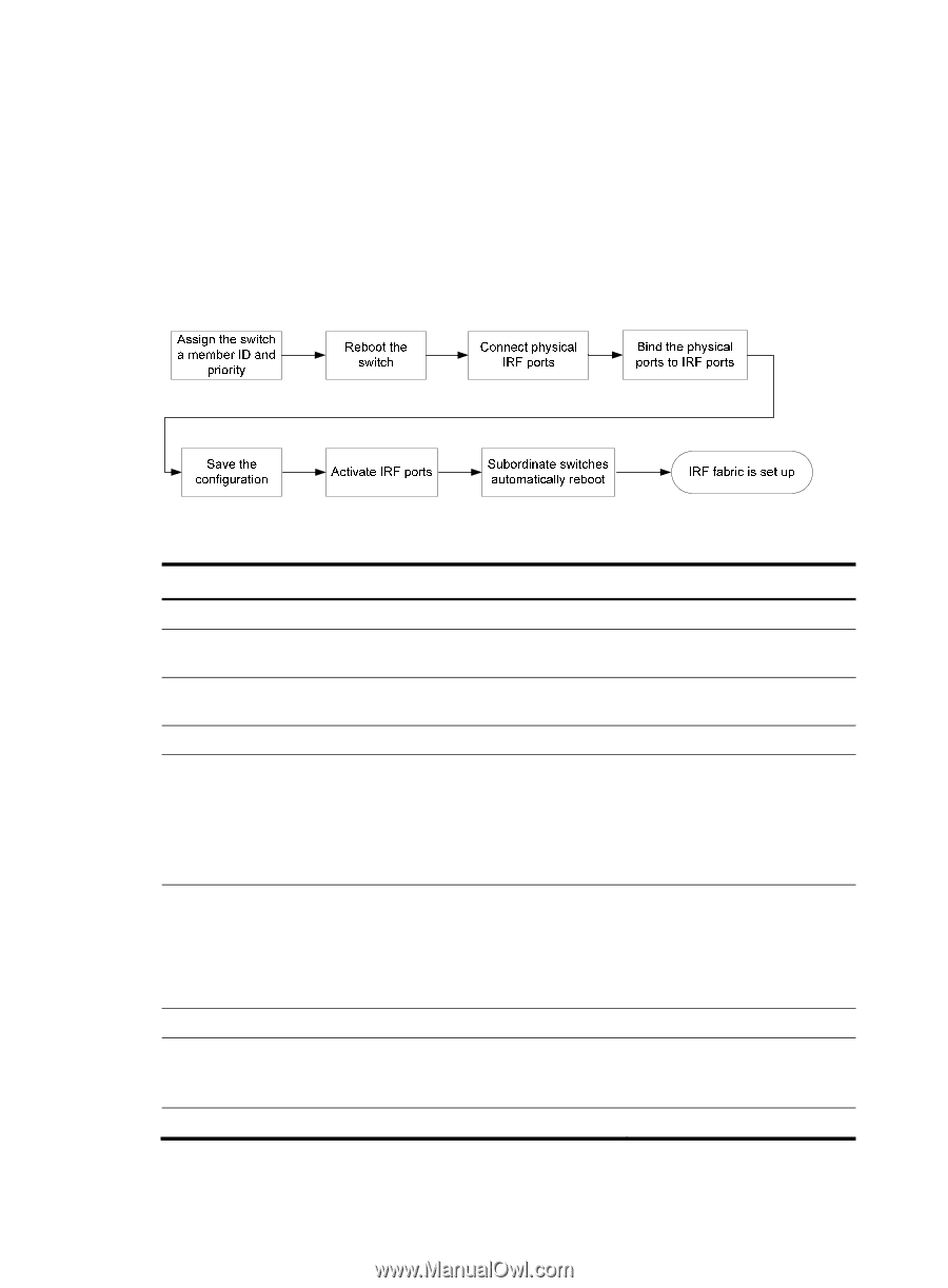
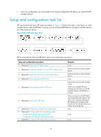
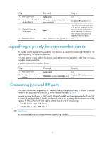
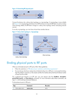
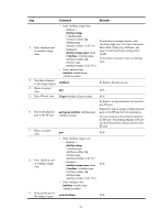
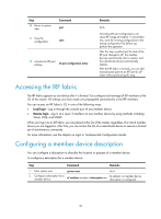
• Save any configuration you have made to the startup configuration file before you reboot the IRF member devices. Setup and configuration task list HP recommends the basic IRF setup procedure in Figure 9. Perform the tasks in this figure on each member device. After the IRF fabric is set up, you can access the IRF fabric to manage its member devices as if they were one device. Figure 9 Basic IRF setup flow chart HP recommends the following IRF fabric setup and configuration procedure: Setup and configuration procedure 1. (Required.) Planning the IRF fabric setup 2. (Required.) Assigning a member ID to each IRF member device 3. (Required.) Specifying a priority for each member device 4. (Required.) Connecting physical IRF ports 5. (Required.) Binding physical ports to IRF ports 6. (Required.) Accessing the IRF fabric 7. (Optional.) Configuring a member device description 8. (Optional.) Configuring IRF link load sharing mode: { Configuring the global load sharing mode { Configuring a port-specific load sharing mode 9. (Optional.) Configuring IRF bridge MAC persistence Remarks N/A Perform this task on each member device. Perform this task on each member device. N/A Perform this task on each member switch. When you complete IRF port binding and activation on all IRF member devices, the IRF fabric is formed. When you log in to the IRF fabric, you are placed at the master's CLI, where you complete subsequent IRF settings and configure other features for the member devices as if they were one device. N/A N/A N/A 15
-
 1
1 -
2
-
3
-
4
-
5
-
6
-
7
-
8
-
9
-
10
-
11
-
12
-
13
-
 14
14 -
 15
15 -
 16
16 -
 17
17 -
 18
18 -
 19
19 -
 20
20 -
 21
21 -
 22
22 -
 23
23 -
 24
24 -
25
-
26
-
27
-
28
-
29
-
30
-
31
-
32
-
33
-
34
-
35
-
36
-
37
-
38
-
39
-
40
-
41
-
42
-
43
-
44
-
45
-
46
-
47
-
48
-
49
-
50
-
51
-
52
-
53
-
54
-
55
-
56
-
57
-
58
-
59
-
60
-
61
-
62
-
63
 |
 |