HP 6125XLG R2306-HP 6125XLG Blade Switch IRF Configuration Guide - Page 21
Specifying a priority for each member device, Connecting physical IRF ports
 |
View all HP 6125XLG manuals
Add to My Manuals
Save this manual to your list of manuals |
Page 21 highlights
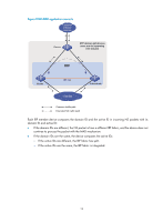
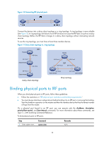
Step 1. Enter system view. 2. Assign a member ID to a member device. Command system-view irf member member-id renumber new-member-id 3. (Optional.) Save the configuration. save 4. Reboot the device. reboot [ slot slot-number ] [ force ] Remarks N/A The default IRF member ID is 1. If you have bound physical ports to IRF ports or assigned member priority, save the configuration before rebooting the device so these settings can continue to take effect after the reboot. N/A Specifying a priority for each member device IRF member priority represents the possibility for a device to be elected the master in an IRF fabric. The higher the priority, the higher the possibility. A member priority change affects the election result at the next master election, but it does not cause immediate master re-election. To specify a priority for a member device: Step 1. Enter system view. 2. Specify a priority for the device. Command Remarks system-view N/A irf member member-id priority priority The default IRF member priority is 1. Connecting physical IRF ports When you connect two neighboring IRF members, connect the physical ports of IRF-port 1 on one member to the physical ports of IRF-port 2 on the other, as shown in Figure 10. Suppose you have four chassis: A, B, C, and D. IRF-port 1 and IRF-port 2 are represented by A1 and A2 on chassis A, represented by B1 and B2 on chassis B, and so on. To connect the four chassis into a ring topology of A-B-C-D(A), the IRF link cabling scheme must be one of the following: • A1-B2, B1-C2, C1-D2, and D1-A2. • A2-B1, B2-C1, C2-D1, and D2-A1. IMPORTANT: No intermediate devices are allowed between neighboring members. 17
-
 1
1 -
2
-
3
-
4
-
5
-
6
-
7
-
8
-
9
-
10
-
11
-
12
-
13
-
14
-
15
-
 16
16 -
 17
17 -
 18
18 -
 19
19 -
 20
20 -
 21
21 -
 22
22 -
 23
23 -
 24
24 -
 25
25 -
 26
26 -
27
-
28
-
29
-
30
-
31
-
32
-
33
-
34
-
35
-
36
-
37
-
38
-
39
-
40
-
41
-
42
-
43
-
44
-
45
-
46
-
47
-
48
-
49
-
50
-
51
-
52
-
53
-
54
-
55
-
56
-
57
-
58
-
59
-
60
-
61
-
62
-
63
 |
 |