HP 6125XLG R2306-HP 6125XLG Blade Switch IRF Configuration Guide - Page 51
ND MAD-enabled IRF configuration example, Network requirements, Configuration procedure
 |
View all HP 6125XLG manuals
Add to My Manuals
Save this manual to your list of manuals |
Page 51 highlights
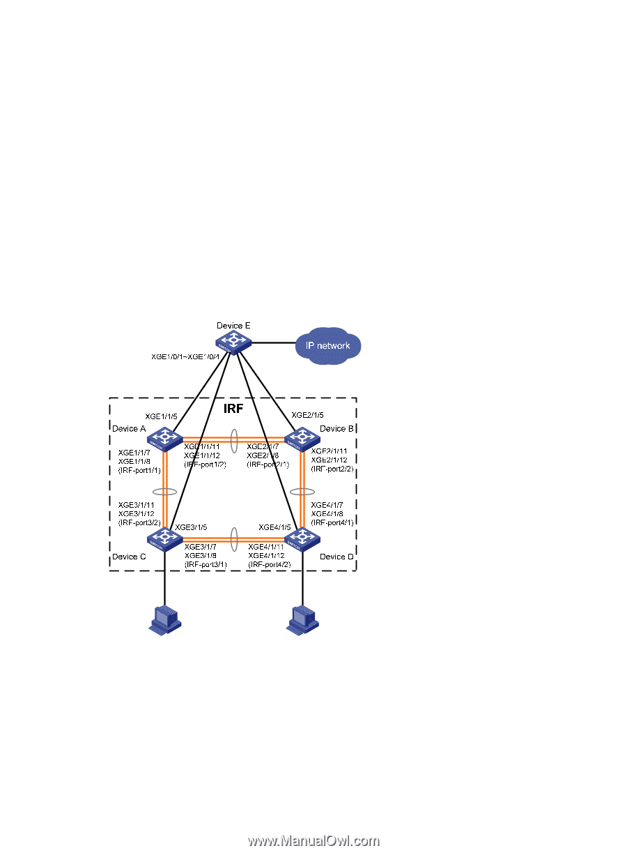
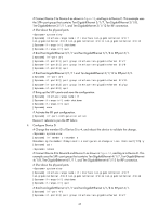
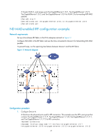
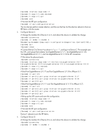
# Create VLAN 3, and assign ports Ten-GigabitEthernet 1/0/1, Ten-GigabitEthernet 1/0/2, Ten-GigabitEthernet 1/0/3, and Ten-GigabitEthernet 1/0/4 to VLAN 3 for forwarding ARP MAD packets. [DeviceE] vlan 3 [DeviceE-vlan3] port ten-gigabitethernet 1/0/1 to ten-gigabitethernet 1/0/4 [DeviceE-vlan3] quit ND MAD-enabled IRF configuration example Network requirements Set up a four-chassis IRF fabric in the IPv6 enterprise network in Figure 17. Configure ND MAD in the IRF fabric and use the links connected to Device E for transmitting ND MAD packets. To prevent loops, run the spanning tree feature between Device E and the IRF fabric. Figure 17 Network diagram Configuration procedure 1. Configure Device A: # Shut down the physical ports used for IRF connection. This example uses the SFP+ port group that contains Ten-GigabitEthernet 1/1/7, Ten-GigabitEthernet 1/1/8, Ten-GigabitEthernet 1/1/11, and Ten-GigabitEthernet 1/1/12 for IRF connection. system-view [Sysname] interface range name irf interface ten-gigabitethernet 1/1/7 ten-gigabitethernet 1/1/8 ten-gigabitethernet 1/1/11 ten-gigabitethernet 1/1/12 47
-
 1
1 -
2
-
3
-
4
-
5
-
6
-
7
-
8
-
9
-
10
-
11
-
12
-
13
-
14
-
15
-
16
-
17
-
18
-
19
-
20
-
21
-
22
-
23
-
24
-
25
-
26
-
27
-
28
-
29
-
30
-
31
-
32
-
33
-
34
-
35
-
36
-
37
-
38
-
39
-
40
-
41
-
42
-
43
-
44
-
45
-
 46
46 -
 47
47 -
 48
48 -
 49
49 -
 50
50 -
 51
51 -
 52
52 -
 53
53 -
 54
54 -
 55
55 -
 56
56 -
57
-
58
-
59
-
60
-
61
-
62
-
63
 |
 |