HP 6125XLG R2306-HP 6125XLG Blade Switch IRF Configuration Guide - Page 6
Network topologies, Basic concepts, IRF member roles, IRF member ID
 |
View all HP 6125XLG manuals
Add to My Manuals
Save this manual to your list of manuals |
Page 6 highlights
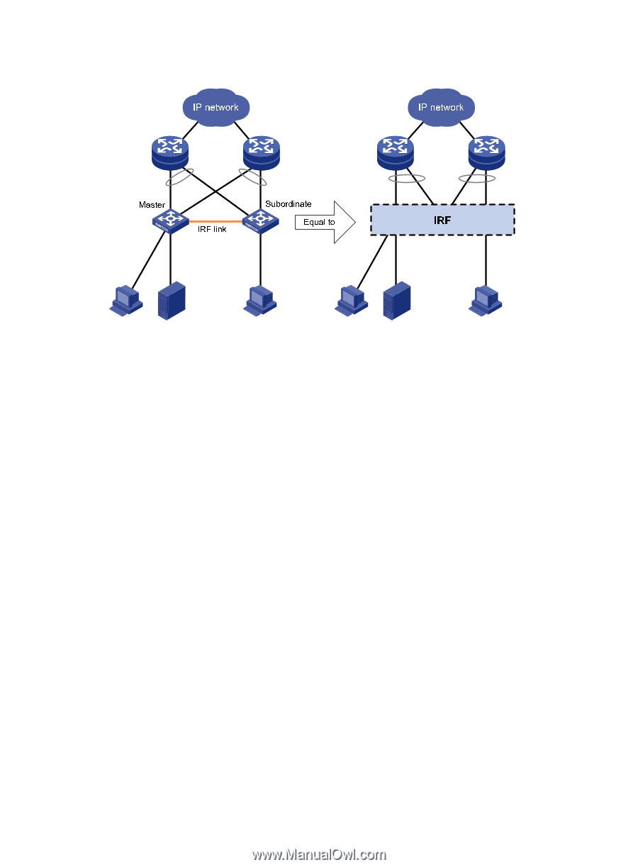
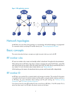
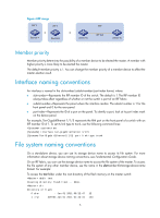
Figure 1 IRF application scenario Network topologies An IRF fabric can use a daisy chain topology or a ring topology. Full meshed topology is not supported. For information about connecting IRF member devices, see "Connecting physical IRF ports." Basic concepts This section describes the basic concepts you might encounter when you work with IRF. IRF member roles IRF uses two member roles: master and standby (called "subordinate" throughout the documentation). When devices form an IRF fabric, they elect a master to manage and control the IRF fabric, and all the other devices back up the master. When the master device fails, the other devices automatically elect a new master. For more information about master election, see "Master election." While backing up the master, all subordinate devices process and forward traffic independently. IRF member ID An IRF fabric uses member IDs to uniquely identify and manage its members. This member ID information is included as the first part of interface numbers and file paths to uniquely identify interfaces and files in an IRF fabric. For more information about interface and file path naming, see "Interface naming conventions" and "File system naming conventions." If two devices have the same IRF member ID, they cannot form an IRF fabric. If the IRF member ID of a device has been used in an IRF fabric, the device cannot join the fabric. 2
-
 1
1 -
 2
2 -
 3
3 -
 4
4 -
 5
5 -
 6
6 -
 7
7 -
 8
8 -
 9
9 -
 10
10 -
 11
11 -
 12
12 -
13
-
14
-
15
-
16
-
17
-
18
-
19
-
20
-
21
-
22
-
23
-
24
-
25
-
26
-
27
-
28
-
29
-
30
-
31
-
32
-
33
-
34
-
35
-
36
-
37
-
38
-
39
-
40
-
41
-
42
-
43
-
44
-
45
-
46
-
47
-
48
-
49
-
50
-
51
-
52
-
53
-
54
-
55
-
56
-
57
-
58
-
59
-
60
-
61
-
62
-
63
 |
 |