HP 6125XLG R2306-HP 6125XLG Blade Switch IRF Configuration Guide - Page 42
BFD MAD-enabled IRF configuration example, Network requirements, Configuration procedure
 |
View all HP 6125XLG manuals
Add to My Manuals
Save this manual to your list of manuals |
Page 42 highlights
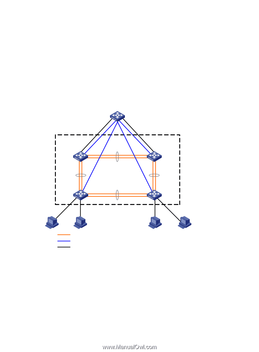
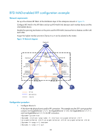
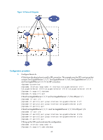
BFD MAD-enabled IRF configuration example Network requirements Set up a four-chassis IRF fabric at the distribution layer of the enterprise network in Figure 15. Configure BFD MAD in the IRF fabric and set up BFD MAD links between each member device and the intermediate device. Disable the spanning tree feature on the ports used for BFD MAD, because the two features conflict with each other. Assign the highest member priority to Device A so it can be elected as the master. Figure 15 Network diagram Device E Device A XGE1/1/7 XGE1/1/8 (IRF-port 1/1) IRF XGE1/0/1 XGE1/0/2 XGE1/0/4 XGE1/0/3 XGE1/1/5 XGE2/1/5 Device B XGE1/1/11 XGE1/1/12 (IRF-port 1/2) XGE2/1/7 XGE2/1/8 (IRF-port 2/1) XGE2/1/11 XGE2/1/12 (IRF-port 2/2) XGE3/1/11 XGE3/1/12 (IRF-port 3/2) Device C XGE3/1/5 XGE3/1/7 XGE3/1/8 (IRF-port 3/1) XGE4/1/5 XGE4/1/11 XGE4/1/12 (IRF-port 4/2) XGE4/1/7 XGE4/1/8 (IRF-port 4/1) Device D IRF link BFD MAD link Data link Configuration procedure 1. Configure Device A: # Shut down the physical ports used for IRF connection. This example uses the SFP+ port group that contains Ten-GigabitEthernet 1/1/7, Ten-GigabitEthernet 1/1/8, Ten-GigabitEthernet 1/1/11, and Ten-GigabitEthernet 1/1/12 for IRF connection. system-view [Sysname] interface range name irf interface ten-gigabitethernet 1/1/7 ten-gigabitethernet 1/1/8 ten-gigabitethernet 1/1/11 ten-gigabitethernet 1/1/12 [Sysname-if-range-irf] shutdown [Sysname-if-range-irf] quit 38
-
 1
1 -
2
-
3
-
4
-
5
-
6
-
7
-
8
-
9
-
10
-
11
-
12
-
13
-
14
-
15
-
16
-
17
-
18
-
19
-
20
-
21
-
22
-
23
-
24
-
25
-
26
-
27
-
28
-
29
-
30
-
31
-
32
-
33
-
34
-
35
-
36
-
 37
37 -
 38
38 -
 39
39 -
 40
40 -
 41
41 -
 42
42 -
 43
43 -
 44
44 -
 45
45 -
 46
46 -
 47
47 -
48
-
49
-
50
-
51
-
52
-
53
-
54
-
55
-
56
-
57
-
58
-
59
-
60
-
61
-
62
-
63
 |
 |