HP 6125XLG R2306-HP 6125XLG Blade Switch IRF Configuration Guide - Page 7
IRF port, Physical IRF port, IRF domain ID, Device A and Device B form IRF fabric 1
 |
View all HP 6125XLG manuals
Add to My Manuals
Save this manual to your list of manuals |
Page 7 highlights
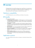
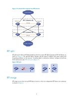
IRF port An IRF port is a logical interface for the connection between IRF member devices. Every IRF-capable device supports two IRF ports. The IRF ports are named IRF-port n/1 and IRF-port n/2, where n is the member ID of the switch. The two IRF ports are referred to as "IRF-port 1" and "IRF-port 2" in this book for simplicity. To use an IRF port, you must bind at least one physical port to it. The physical ports assigned to an IRF port automatically form an aggregate IRF link. An IRF port goes down only if all its physical IRF ports are down. Physical IRF port Physical IRF ports connect IRF member devices and must be bound to an IRF port. They forward the IRF protocol packets between IRF member devices and the data packets that must travel across IRF member devices. For more information about physical ports that can be used for IRF links, see "IRF physical port restrictions and binding requirements." IRF domain ID One IRF fabric forms one IRF domain. IRF uses IRF domain IDs to uniquely identify IRF fabrics and prevent IRF fabrics from interfering with one another. As shown in Figure 2, Device A and Device B form IRF fabric 1, and Device C and Device D form IRF fabric 2. The fabrics have LACP MAD links between them. When a member device in one IRF fabric receives an extended LACP packet for MAD, it looks at the domain ID in the packet to see whether the packet is from the local IRF fabric or from a different IRF fabric. Then, the device can handle the packet correctly. 3
-
 1
1 -
 2
2 -
 3
3 -
 4
4 -
 5
5 -
 6
6 -
 7
7 -
 8
8 -
 9
9 -
 10
10 -
 11
11 -
 12
12 -
13
-
14
-
15
-
16
-
17
-
18
-
19
-
20
-
21
-
22
-
23
-
24
-
25
-
26
-
27
-
28
-
29
-
30
-
31
-
32
-
33
-
34
-
35
-
36
-
37
-
38
-
39
-
40
-
41
-
42
-
43
-
44
-
45
-
46
-
47
-
48
-
49
-
50
-
51
-
52
-
53
-
54
-
55
-
56
-
57
-
58
-
59
-
60
-
61
-
62
-
63
 |
 |