HP 6125XLG R2306-HP 6125XLG Blade Switch IRF Configuration Guide - Page 20
Planning the IRF fabric setup, Assigning a member ID to each IRF member device
 |
View all HP 6125XLG manuals
Add to My Manuals
Save this manual to your list of manuals |
Page 20 highlights
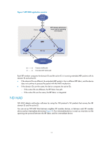
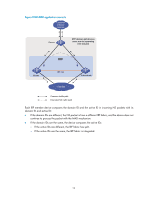
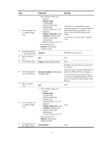
Setup and configuration procedure 10. (Optional.) Enabling software auto-update for software image synchronization 11. (Optional.) Setting the IRF link down report delay 12. (Required.) Configuring MAD: { Configuring LACP MAD { Configuring BFD MAD { Configuring ARP MAD { Configuring ND MAD { Excluding a port from the shutdown action upon detection of multi-active collision 13. (Optional.) Recovering an IRF fabric Remarks HP recommends enabling software auto-update to make sure system software image synchronization. N/A MAD mechanisms are independent of one another. You can configure at least one MAD mechanism for an IRF fabric. N/A Planning the IRF fabric setup Consider the following items when you plan an IRF fabric: • Hardware compatibility and restrictions • IRF fabric size • Master switch • IRF physical ports • Member ID and priority assignment scheme • Fabric topology and cabling scheme For more information about hardware and cabling, see the switch installation guide. Assigning a member ID to each IRF member device CAUTION: In an IRF fabric, changing IRF member IDs might cause undesirable configuration changes and even data loss. Before you do that, back up the configuration and make sure you fully understand the impact on your network. For example, all member switches in an IRF fabric are the same model. If you swapped the IDs of any two members, their interface settings would also be swapped. By default, the member IDs of all switches are 1. To create an IRF fabric, you must assign a unique IRF member ID to each member device. Devices with the same member ID cannot join the same IRF fabric. Perform this task before the IRF fabric is formed. To prevent any undesirable configuration change or data loss, avoid changing member IDs after the IRF fabric is formed. The new member ID takes effect at a reboot. After the switch reboots, the settings on all member ID-related physical resources (including common physical network ports) are removed and require reconfiguration, regardless of whether you have saved the configuration. To assign a member ID to a device: 16
-
 1
1 -
2
-
3
-
4
-
5
-
6
-
7
-
8
-
9
-
10
-
11
-
12
-
13
-
14
-
 15
15 -
 16
16 -
 17
17 -
 18
18 -
 19
19 -
 20
20 -
 21
21 -
 22
22 -
 23
23 -
 24
24 -
 25
25 -
26
-
27
-
28
-
29
-
30
-
31
-
32
-
33
-
34
-
35
-
36
-
37
-
38
-
39
-
40
-
41
-
42
-
43
-
44
-
45
-
46
-
47
-
48
-
49
-
50
-
51
-
52
-
53
-
54
-
55
-
56
-
57
-
58
-
59
-
60
-
61
-
62
-
63
 |
 |