HP 6125XLG R2306-HP 6125XLG Blade Switch IRF Configuration Guide - Page 22
Binding physical ports to IRF ports
 |
View all HP 6125XLG manuals
Add to My Manuals
Save this manual to your list of manuals |
Page 22 highlights
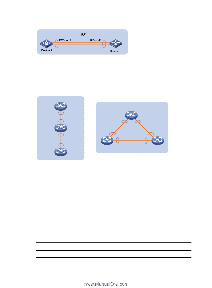
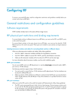
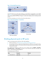
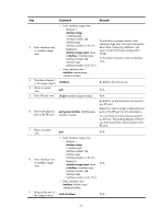
Figure 10 Connecting IRF physical ports Connect the devices into a daisy chain topology or a ring topology. A ring topology is more reliable (see Figure 11). In ring topology, the failure of one IRF link does not cause the IRF fabric to split as in daisy chain topology. Rather, the IRF fabric changes to a daisy chain topology without interrupting network services. To use the ring topology, you must have at least three member devices. Figure 11 Daisy chain topology vs. ring topology Master IRF IRF-Port2 Master IRF-Port1 Subordinate IRF-Port2 IRF-Port1 IRF-Port2 IRF IRF-Port2 IRF-Port1 IRF-Port1 Subordinate Daisy chain topology IRF-Port1 Subordinate IRF-Port2 Subordinate Ring topology Binding physical ports to IRF ports When you bind physical ports to IRF ports, follow these guidelines: • Follow the restrictions in "IRF physical port restrictions and binding requirements." • You must always shut down a physical port before binding it to an IRF port or removing the binding. Start the shutdown operation on the master and then the member device that has the fewest number of hops from the master. On a physical port bound to an IRF port, you can execute only the shutdown, description, priority-flow-control, and flow-interval commands. For more information about these commands, see Layer 2-LAN Switching Command Reference. To bind physical ports to IRF ports: Step 1. Enter system view. Command system-view Remarks N/A 18
-
 1
1 -
2
-
3
-
4
-
5
-
6
-
7
-
8
-
9
-
10
-
11
-
12
-
13
-
14
-
15
-
16
-
 17
17 -
 18
18 -
 19
19 -
 20
20 -
 21
21 -
 22
22 -
 23
23 -
 24
24 -
 25
25 -
 26
26 -
 27
27 -
28
-
29
-
30
-
31
-
32
-
33
-
34
-
35
-
36
-
37
-
38
-
39
-
40
-
41
-
42
-
43
-
44
-
45
-
46
-
47
-
48
-
49
-
50
-
51
-
52
-
53
-
54
-
55
-
56
-
57
-
58
-
59
-
60
-
61
-
62
-
63
 |
 |