HP LaserJet 4v/mv HP LaserJet 4V and 4MV Printer - User’s Guide, C314 - Page 21
HP LaserJet 4V/4MV Printer Parts - fuser
 |
View all HP LaserJet 4v/mv manuals
Add to My Manuals
Save this manual to your list of manuals |
Page 21 highlights
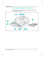
HP LaserJet 4V/4MV Printer Parts The following illustrations show the locations and names of key printer parts (Figures 1-5 through 1-7). 1 23 4 5 12 11 10 98 76 Figure 1-5 Front and right side view with MP Tray open 1. Front cover 2. Control panel 3. Output bin 4. Adjustable paper stop 5. 250-sheet 11x17 or A3 Paper Cassette 6. ON/OFF switch 7. 250-sheet Letter or A4 Paper Cassette 8. Front cover release button 9. Multipurpose (MP) Tray 10. MP Tray extension 11. MP Tray paper width guides 12. Fuser assembly door 1-10 About Your Printer
-
 1
1 -
2
-
3
-
4
-
5
-
6
-
7
-
8
-
9
-
10
-
11
-
12
-
13
-
14
-
15
-
 16
16 -
 17
17 -
 18
18 -
 19
19 -
 20
20 -
 21
21 -
 22
22 -
 23
23 -
 24
24 -
 25
25 -
 26
26 -
27
-
28
-
29
-
30
-
31
-
32
-
33
-
34
-
35
-
36
-
37
-
38
-
39
-
40
-
41
-
42
-
43
-
44
-
45
-
46
-
47
-
48
-
49
-
50
-
51
-
52
-
53
-
54
-
55
-
56
-
57
-
58
-
59
-
60
-
61
-
62
-
63
-
64
-
65
-
66
-
67
-
68
-
69
-
70
-
71
-
72
-
73
-
74
-
75
-
76
-
77
-
78
-
79
-
80
-
81
-
82
-
83
-
84
-
85
-
86
-
87
-
88
-
89
-
90
-
91
-
92
-
93
-
94
-
95
-
96
-
97
-
98
-
99
-
100
-
101
-
102
-
103
-
104
-
105
-
106
-
107
-
108
-
109
-
110
-
111
-
112
-
113
-
114
-
115
-
116
-
117
-
118
-
119
-
120
-
121
-
122
-
123
-
124
-
125
-
126
-
127
-
128
-
129
-
130
-
131
-
132
-
133
-
134
-
135
-
136
-
137
-
138
-
139
-
140
-
141
-
142
-
143
-
144
-
145
-
146
-
147
-
148
-
149
-
150
-
151
-
152
-
153
-
154
-
155
-
156
-
157
-
158
-
159
-
160
-
161
-
162
-
163
-
164
-
165
-
166
-
167
-
168
-
169
-
170
-
171
 |
 |

HP LaserJet 4V/4MV Printer Parts
The following illustrations show the locations and names of key printer
parts (Figures 1-5 through 1-7).
1.
Front cover
7.
250-sheet Letter or A4 Paper Cassette
2.
Control panel
8.
Front cover release button
3.
Output bin
9.
Multipurpose (MP) Tray
4.
Adjustable paper stop
10.
MP Tray extension
5.
250-sheet 11x17 or A3 Paper Cassette
11.
MP Tray paper width guides
6.
ON/OFF switch
12.
Fuser assembly door
1
6
8
7
9
3
2
4
5
12
11
10
Figure 1-5
Front and right side view with MP Tray open
1-10 About Your Printer