HP Pro 3330 HP Pro 3330 Microtower PC, HP Pro 3330 Small Form Factor PC, and H - Page 126
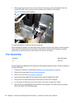
Fan Assembly
 |
View all HP Pro 3330 manuals
Add to My Manuals
Save this manual to your list of manuals |
Page 126 highlights
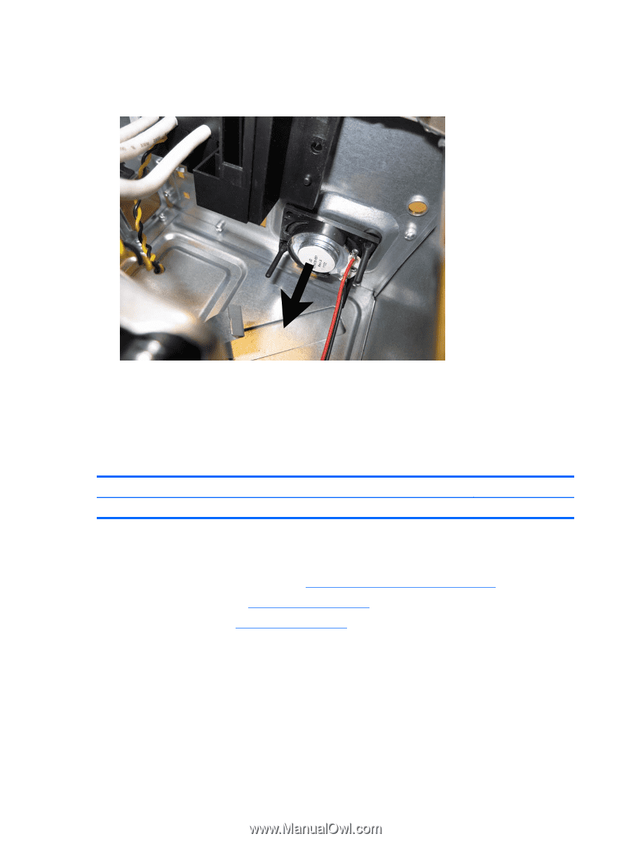
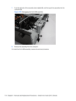
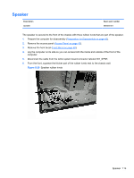
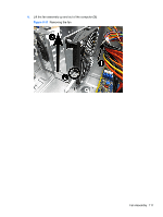
7. While squeezing the outer rivet, from the inside of the chassis, pull the associated inside rivet toward the inside of the computer until the outside rivet is pulled into the chassis. Figure 8-30 Removing the speaker To install the speaker, reverse the removal procedures. When installing the speaker, from the inside of the computer, feed the outer rubber rivets through the holes in the front chassis wall, and the pull the rivets from the outside until the speaker is properly seated with the narrow part of the rivets sitting in the holes in the chassis. Fan Assembly Description Fan Spare part number 656834-001 The fan assembly is attached to the inside floor of the chassis using two screws. The fan is inside of a removal metal cage. 1. Prepare the computer for disassembly (Preparation for Disassembly on page 90). 2. Remove the access panel (Access Panel on page 90). 3. Remove the front bezel (Front Bezel on page 92). 4. Disconnect the fan cable from the system board connector labeled SYS_FAN. 5. Remove the Torx screw that secures the left side of the fan to the computer. 6. Cut the plastic tie (1) that secures the fan cable to the power supply power cables. 7. Remove the two screws (2) that secure the fan to the computer. The screw near the computer side is not shown in the following image. 116 Chapter 8 Removal and Replacement Procedures - Small Form Factor (SFF) Chassis
-
 1
1 -
2
-
3
-
4
-
5
-
6
-
7
-
8
-
9
-
10
-
11
-
12
-
13
-
14
-
15
-
16
-
17
-
18
-
19
-
20
-
21
-
22
-
23
-
24
-
25
-
26
-
27
-
28
-
29
-
30
-
31
-
32
-
33
-
34
-
35
-
36
-
37
-
38
-
39
-
40
-
41
-
42
-
43
-
44
-
45
-
46
-
47
-
48
-
49
-
50
-
51
-
52
-
53
-
54
-
55
-
56
-
57
-
58
-
59
-
60
-
61
-
62
-
63
-
64
-
65
-
66
-
67
-
68
-
69
-
70
-
71
-
72
-
73
-
74
-
75
-
76
-
77
-
78
-
79
-
80
-
81
-
82
-
83
-
84
-
85
-
86
-
87
-
88
-
89
-
90
-
91
-
92
-
93
-
94
-
95
-
96
-
97
-
98
-
99
-
100
-
101
-
102
-
103
-
104
-
105
-
106
-
107
-
108
-
109
-
110
-
111
-
112
-
113
-
114
-
115
-
116
-
117
-
118
-
119
-
120
-
 121
121 -
 122
122 -
 123
123 -
 124
124 -
 125
125 -
 126
126 -
 127
127 -
 128
128 -
 129
129 -
 130
130 -
 131
131 -
132
-
133
-
134
-
135
-
136
-
137
-
138
-
139
-
140
-
141
-
142
-
143
-
144
-
145
-
146
-
147
-
148
-
149
-
150
-
151
-
152
-
153
-
154
-
155
-
156
-
157
-
158
-
159
-
160
-
161
-
162
-
163
-
164
-
165
-
166
-
167
-
168
-
169
-
170
-
171
-
172
-
173
-
174
-
175
-
176
-
177
-
178
-
179
-
180
-
181
-
182
-
183
-
184
-
185
-
186
-
187
-
188
-
189
-
190
-
191
-
192
-
193
-
194
-
195
-
196
-
197
-
198
-
199
-
200
-
201
-
202
-
203
-
204
-
205
-
206
-
207
-
208
 |
 |