HP Pro 3330 HP Pro 3330 Microtower PC, HP Pro 3330 Small Form Factor PC, and H - Page 90
Fan Sink Assembly - mt processor
 |
View all HP Pro 3330 manuals
Add to My Manuals
Save this manual to your list of manuals |
Page 90 highlights
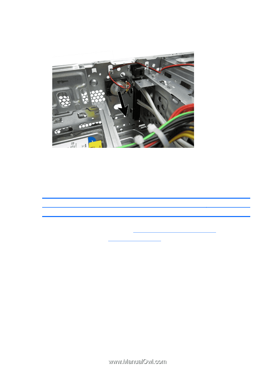
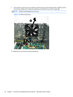
7. While squeezing the outer rivet, from the inside of the chassis, pull the associated inside rivet toward the inside of the computer until the outside rivet is pulled into the chassis. Figure 7-38 Removing the speaker To install the speaker, reverse the removal procedures. When installing the speaker, from the inside of the computer, feed the outer rubber rivets through the holes in the front chassis wall, and the pull the rivets from the outside until the speaker is properly seated with the narrow part of the rivets sitting in the holes in the chassis. Fan Sink Assembly Description Fan sink for use in models with Intel processors Spare part number 667727-001 1. Prepare the computer for disassembly (Preparation for Disassembly on page 42). 2. Remove the access panel (Access Panel on page 43). 3. Lay the computer on its side with the rear facing toward you. 4. Loosen the four captive Torx screws that secure the fan sink to the system board. 80 Chapter 7 Removal and Replacement Procedures - Microtower (MT) Chassis
-
 1
1 -
2
-
3
-
4
-
5
-
6
-
7
-
8
-
9
-
10
-
11
-
12
-
13
-
14
-
15
-
16
-
17
-
18
-
19
-
20
-
21
-
22
-
23
-
24
-
25
-
26
-
27
-
28
-
29
-
30
-
31
-
32
-
33
-
34
-
35
-
36
-
37
-
38
-
39
-
40
-
41
-
42
-
43
-
44
-
45
-
46
-
47
-
48
-
49
-
50
-
51
-
52
-
53
-
54
-
55
-
56
-
57
-
58
-
59
-
60
-
61
-
62
-
63
-
64
-
65
-
66
-
67
-
68
-
69
-
70
-
71
-
72
-
73
-
74
-
75
-
76
-
77
-
78
-
79
-
80
-
81
-
82
-
83
-
84
-
 85
85 -
 86
86 -
 87
87 -
 88
88 -
 89
89 -
 90
90 -
 91
91 -
 92
92 -
 93
93 -
 94
94 -
 95
95 -
96
-
97
-
98
-
99
-
100
-
101
-
102
-
103
-
104
-
105
-
106
-
107
-
108
-
109
-
110
-
111
-
112
-
113
-
114
-
115
-
116
-
117
-
118
-
119
-
120
-
121
-
122
-
123
-
124
-
125
-
126
-
127
-
128
-
129
-
130
-
131
-
132
-
133
-
134
-
135
-
136
-
137
-
138
-
139
-
140
-
141
-
142
-
143
-
144
-
145
-
146
-
147
-
148
-
149
-
150
-
151
-
152
-
153
-
154
-
155
-
156
-
157
-
158
-
159
-
160
-
161
-
162
-
163
-
164
-
165
-
166
-
167
-
168
-
169
-
170
-
171
-
172
-
173
-
174
-
175
-
176
-
177
-
178
-
179
-
180
-
181
-
182
-
183
-
184
-
185
-
186
-
187
-
188
-
189
-
190
-
191
-
192
-
193
-
194
-
195
-
196
-
197
-
198
-
199
-
200
-
201
-
202
-
203
-
204
-
205
-
206
-
207
-
208
 |
 |