HP Pro 3330 HP Pro 3330 Microtower PC, HP Pro 3330 Small Form Factor PC, and H - Page 132
Caution,
 |
View all HP Pro 3330 manuals
Add to My Manuals
Save this manual to your list of manuals |
Page 132 highlights
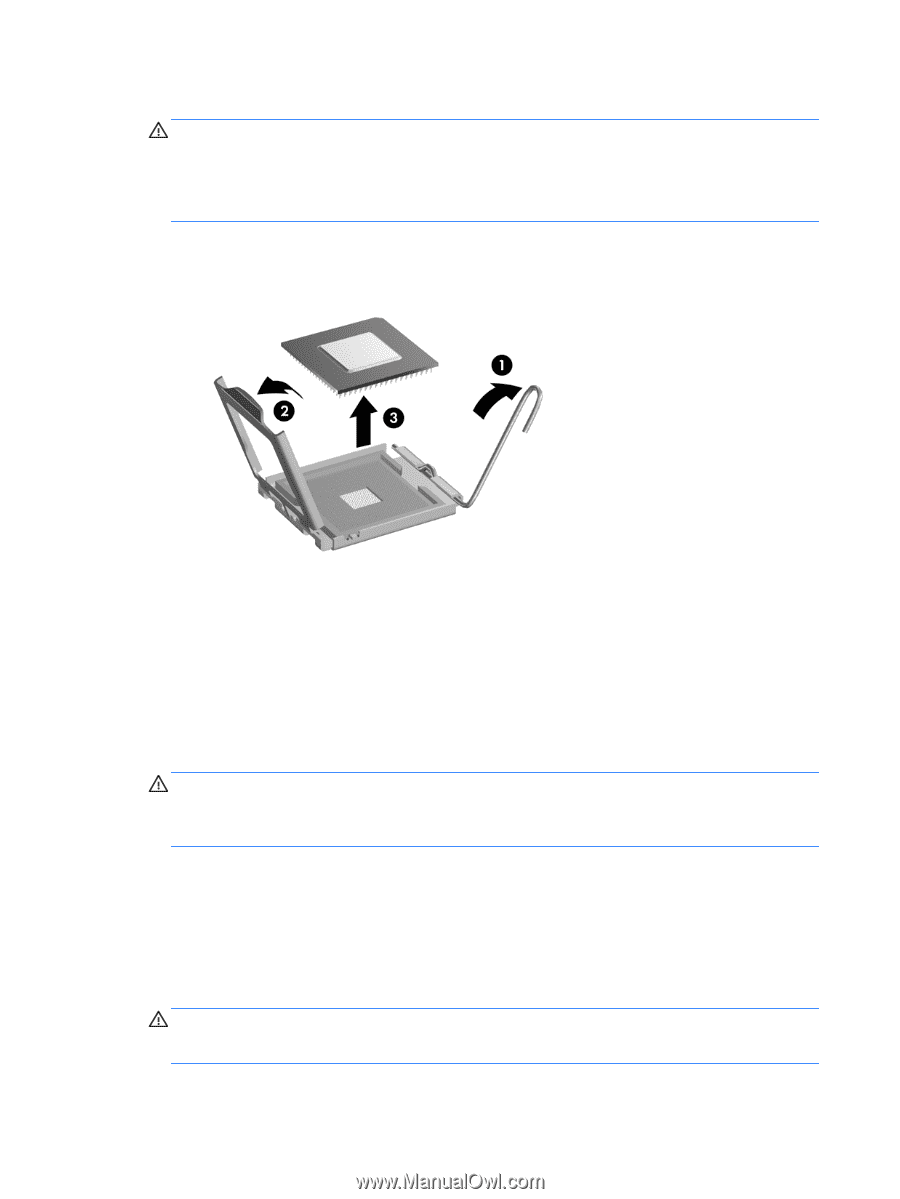
6. Carefully lift the processor from the socket (3). CAUTION: Do NOT handle the pins in the processor socket. These pins are very fragile and handling them could cause irreparable damage. Once pins are damaged it may be necessary to replace the system board. The heat sink must be installed within 24 hours of installing the processor to prevent damage to the processor's solder connections. Figure 8-35 Removing the processor To install a new processor: 1. Place the processor in its socket and close the retainer. Make sure the slot in the processor fits into the post on the socket. 2. Secure the locking lever. If reusing the existing heat sink, go to step 3. If using a new heat sink, go to step 6. 3. If reusing the existing fan sink, clean the bottom of the fan sink with the alcohol pad provided in the spares kit. CAUTION: Before reinstalling the fan sink you must clean the top of the processor and the bottom of the fan sink with an alcohol pad supplied in the spares kit. After the alcohol has evaporated, apply thermal grease to the top of the processor from the syringe supplied in the spares kit. 4. Apply the thermal grease provided in the spares kit to the top of the processor and install the fan sink atop the processor. 5. Go to step 7. 6. If using a new fan sink, remove the protective covering from the bottom of the fan sink and place it in position atop the processor. 7. Secure the fan sink to the system board and system board tray. CAUTION: Fan sink retaining screws should be tightened in diagonally opposite pairs (as in an X) to evenly seat the fan sink on the processor. This is especially important as the pins on the socket are very fragile and any damage to them may require replacing the system board. 122 Chapter 8 Removal and Replacement Procedures - Small Form Factor (SFF) Chassis
-
 1
1 -
2
-
3
-
4
-
5
-
6
-
7
-
8
-
9
-
10
-
11
-
12
-
13
-
14
-
15
-
16
-
17
-
18
-
19
-
20
-
21
-
22
-
23
-
24
-
25
-
26
-
27
-
28
-
29
-
30
-
31
-
32
-
33
-
34
-
35
-
36
-
37
-
38
-
39
-
40
-
41
-
42
-
43
-
44
-
45
-
46
-
47
-
48
-
49
-
50
-
51
-
52
-
53
-
54
-
55
-
56
-
57
-
58
-
59
-
60
-
61
-
62
-
63
-
64
-
65
-
66
-
67
-
68
-
69
-
70
-
71
-
72
-
73
-
74
-
75
-
76
-
77
-
78
-
79
-
80
-
81
-
82
-
83
-
84
-
85
-
86
-
87
-
88
-
89
-
90
-
91
-
92
-
93
-
94
-
95
-
96
-
97
-
98
-
99
-
100
-
101
-
102
-
103
-
104
-
105
-
106
-
107
-
108
-
109
-
110
-
111
-
112
-
113
-
114
-
115
-
116
-
117
-
118
-
119
-
120
-
121
-
122
-
123
-
124
-
125
-
126
-
 127
127 -
 128
128 -
 129
129 -
 130
130 -
 131
131 -
 132
132 -
 133
133 -
 134
134 -
 135
135 -
 136
136 -
 137
137 -
138
-
139
-
140
-
141
-
142
-
143
-
144
-
145
-
146
-
147
-
148
-
149
-
150
-
151
-
152
-
153
-
154
-
155
-
156
-
157
-
158
-
159
-
160
-
161
-
162
-
163
-
164
-
165
-
166
-
167
-
168
-
169
-
170
-
171
-
172
-
173
-
174
-
175
-
176
-
177
-
178
-
179
-
180
-
181
-
182
-
183
-
184
-
185
-
186
-
187
-
188
-
189
-
190
-
191
-
192
-
193
-
194
-
195
-
196
-
197
-
198
-
199
-
200
-
201
-
202
-
203
-
204
-
205
-
206
-
207
-
208
 |
 |