HP Pro 3330 HP Pro 3330 Microtower PC, HP Pro 3330 Small Form Factor PC, and H - Page 129
Fan Sink, Fan sink retaining screws should be removed in diagonally opposite pairs as in an
 |
View all HP Pro 3330 manuals
Add to My Manuals
Save this manual to your list of manuals |
Page 129 highlights
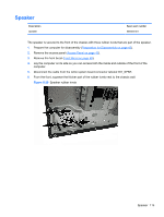
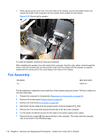
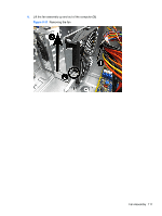
Fan Sink Description Fan sink Spare part number 667727-001 The fan sink is secured atop the processor with four captive Torx screws. A fan cable connects to the system board. 1. Prepare the computer for disassembly (Preparation for Disassembly on page 90). 2. Remove the access panel (Access Panel on page 90). 3. Rotate the drive cage to its upright position. 4. Loosen the four captive screws that secure the fan sink to the system board tray. CAUTION: Fan sink retaining screws should be removed in diagonally opposite pairs (as in an X) to even the downward forces on the processor. This is especially important as the pins on the socket are very fragile and any damage to them may require replacing the system board. Figure 8-33 Loosening the fan sink screws Fan Sink 119
-
 1
1 -
2
-
3
-
4
-
5
-
6
-
7
-
8
-
9
-
10
-
11
-
12
-
13
-
14
-
15
-
16
-
17
-
18
-
19
-
20
-
21
-
22
-
23
-
24
-
25
-
26
-
27
-
28
-
29
-
30
-
31
-
32
-
33
-
34
-
35
-
36
-
37
-
38
-
39
-
40
-
41
-
42
-
43
-
44
-
45
-
46
-
47
-
48
-
49
-
50
-
51
-
52
-
53
-
54
-
55
-
56
-
57
-
58
-
59
-
60
-
61
-
62
-
63
-
64
-
65
-
66
-
67
-
68
-
69
-
70
-
71
-
72
-
73
-
74
-
75
-
76
-
77
-
78
-
79
-
80
-
81
-
82
-
83
-
84
-
85
-
86
-
87
-
88
-
89
-
90
-
91
-
92
-
93
-
94
-
95
-
96
-
97
-
98
-
99
-
100
-
101
-
102
-
103
-
104
-
105
-
106
-
107
-
108
-
109
-
110
-
111
-
112
-
113
-
114
-
115
-
116
-
117
-
118
-
119
-
120
-
121
-
122
-
123
-
 124
124 -
 125
125 -
 126
126 -
 127
127 -
 128
128 -
 129
129 -
 130
130 -
 131
131 -
 132
132 -
 133
133 -
 134
134 -
135
-
136
-
137
-
138
-
139
-
140
-
141
-
142
-
143
-
144
-
145
-
146
-
147
-
148
-
149
-
150
-
151
-
152
-
153
-
154
-
155
-
156
-
157
-
158
-
159
-
160
-
161
-
162
-
163
-
164
-
165
-
166
-
167
-
168
-
169
-
170
-
171
-
172
-
173
-
174
-
175
-
176
-
177
-
178
-
179
-
180
-
181
-
182
-
183
-
184
-
185
-
186
-
187
-
188
-
189
-
190
-
191
-
192
-
193
-
194
-
195
-
196
-
197
-
198
-
199
-
200
-
201
-
202
-
203
-
204
-
205
-
206
-
207
-
208
 |
 |