HP Pro 3330 HP Pro 3330 Microtower PC, HP Pro 3330 Small Form Factor PC, and H - Page 85
Power Switch/LED Assembly, Preparation for Disassembly, on Access Panel, Front Bezel
 |
View all HP Pro 3330 manuals
Add to My Manuals
Save this manual to your list of manuals |
Page 85 highlights
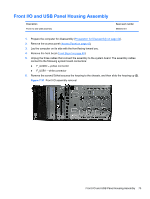
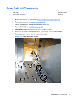
Power Switch/LED Assembly Description Power switch/LED assembly Spare part number 657105-001 1. Prepare the computer for disassembly (Preparation for Disassembly on page 42). 2. Remove the access panel (Access Panel on page 43). 3. Lay the computer on its side with the front facing toward you. 4. Remove the front bezel (Front Bezel on page 45). 5. Remove the optical drive (Removing an Optical Drive on page 63). 6. Disconnect the braided cables from the black system board connector labeled JFP1. 7. Remove the cable from the clips in the optical drive cage. Figure 7-33 Power switch cable routing Power Switch/LED Assembly 75
-
 1
1 -
2
-
3
-
4
-
5
-
6
-
7
-
8
-
9
-
10
-
11
-
12
-
13
-
14
-
15
-
16
-
17
-
18
-
19
-
20
-
21
-
22
-
23
-
24
-
25
-
26
-
27
-
28
-
29
-
30
-
31
-
32
-
33
-
34
-
35
-
36
-
37
-
38
-
39
-
40
-
41
-
42
-
43
-
44
-
45
-
46
-
47
-
48
-
49
-
50
-
51
-
52
-
53
-
54
-
55
-
56
-
57
-
58
-
59
-
60
-
61
-
62
-
63
-
64
-
65
-
66
-
67
-
68
-
69
-
70
-
71
-
72
-
73
-
74
-
75
-
76
-
77
-
78
-
79
-
 80
80 -
 81
81 -
 82
82 -
 83
83 -
 84
84 -
 85
85 -
 86
86 -
 87
87 -
 88
88 -
 89
89 -
 90
90 -
91
-
92
-
93
-
94
-
95
-
96
-
97
-
98
-
99
-
100
-
101
-
102
-
103
-
104
-
105
-
106
-
107
-
108
-
109
-
110
-
111
-
112
-
113
-
114
-
115
-
116
-
117
-
118
-
119
-
120
-
121
-
122
-
123
-
124
-
125
-
126
-
127
-
128
-
129
-
130
-
131
-
132
-
133
-
134
-
135
-
136
-
137
-
138
-
139
-
140
-
141
-
142
-
143
-
144
-
145
-
146
-
147
-
148
-
149
-
150
-
151
-
152
-
153
-
154
-
155
-
156
-
157
-
158
-
159
-
160
-
161
-
162
-
163
-
164
-
165
-
166
-
167
-
168
-
169
-
170
-
171
-
172
-
173
-
174
-
175
-
176
-
177
-
178
-
179
-
180
-
181
-
182
-
183
-
184
-
185
-
186
-
187
-
188
-
189
-
190
-
191
-
192
-
193
-
194
-
195
-
196
-
197
-
198
-
199
-
200
-
201
-
202
-
203
-
204
-
205
-
206
-
207
-
208
 |
 |

Power Switch/LED Assembly
Description
Spare part number
Power switch/LED assembly
657105-001
1.
Prepare the computer for disassembly (
Preparation for Disassembly
on page
42
).
2.
Remove the access panel (
Access Panel
on page
43
).
3.
Lay the computer on its side with the front facing toward you.
4.
Remove the front bezel (
Front Bezel
on page
45
).
5.
Remove the optical drive (
Removing an Optical Drive
on page
63
).
6.
Disconnect the braided cables from the black system board connector labeled JFP1.
7.
Remove the cable from the clips in the optical drive cage.
Figure 7-33
Power switch cable routing
Power Switch/LED Assembly
75