HP Pro 3330 HP Pro 3330 Microtower PC, HP Pro 3330 Small Form Factor PC, and H - Page 83
Front I/O and USB Panel Housing Assembly
 |
View all HP Pro 3330 manuals
Add to My Manuals
Save this manual to your list of manuals |
Page 83 highlights
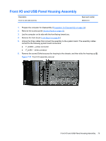
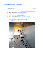
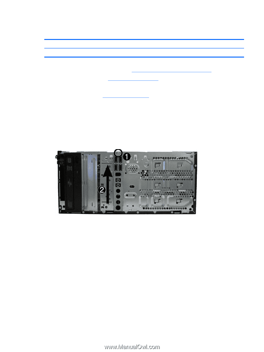
Front I/O and USB Panel Housing Assembly Description Front I/O and USB assembly Spare part number 668572-001 1. Prepare the computer for disassembly (Preparation for Disassembly on page 42). 2. Remove the access panel (Access Panel on page 43) 3. Lay the computer on its side with the front facing toward you. 4. Remove the front bezel (Front Bezel on page 45). 5. Unplug the three cables that connect the assembly to the system board. The assembly cables connect to the following system board connectors: ● F_AUDIO - yellow connector ● F_USB1 - white connector 6. Remove the screw (1) that secures the housing to the chassis, and then slide the housing up (2). Figure 7-31 Front I/O assembly removal Front I/O and USB Panel Housing Assembly 73
-
 1
1 -
2
-
3
-
4
-
5
-
6
-
7
-
8
-
9
-
10
-
11
-
12
-
13
-
14
-
15
-
16
-
17
-
18
-
19
-
20
-
21
-
22
-
23
-
24
-
25
-
26
-
27
-
28
-
29
-
30
-
31
-
32
-
33
-
34
-
35
-
36
-
37
-
38
-
39
-
40
-
41
-
42
-
43
-
44
-
45
-
46
-
47
-
48
-
49
-
50
-
51
-
52
-
53
-
54
-
55
-
56
-
57
-
58
-
59
-
60
-
61
-
62
-
63
-
64
-
65
-
66
-
67
-
68
-
69
-
70
-
71
-
72
-
73
-
74
-
75
-
76
-
77
-
 78
78 -
 79
79 -
 80
80 -
 81
81 -
 82
82 -
 83
83 -
 84
84 -
 85
85 -
 86
86 -
 87
87 -
 88
88 -
89
-
90
-
91
-
92
-
93
-
94
-
95
-
96
-
97
-
98
-
99
-
100
-
101
-
102
-
103
-
104
-
105
-
106
-
107
-
108
-
109
-
110
-
111
-
112
-
113
-
114
-
115
-
116
-
117
-
118
-
119
-
120
-
121
-
122
-
123
-
124
-
125
-
126
-
127
-
128
-
129
-
130
-
131
-
132
-
133
-
134
-
135
-
136
-
137
-
138
-
139
-
140
-
141
-
142
-
143
-
144
-
145
-
146
-
147
-
148
-
149
-
150
-
151
-
152
-
153
-
154
-
155
-
156
-
157
-
158
-
159
-
160
-
161
-
162
-
163
-
164
-
165
-
166
-
167
-
168
-
169
-
170
-
171
-
172
-
173
-
174
-
175
-
176
-
177
-
178
-
179
-
180
-
181
-
182
-
183
-
184
-
185
-
186
-
187
-
188
-
189
-
190
-
191
-
192
-
193
-
194
-
195
-
196
-
197
-
198
-
199
-
200
-
201
-
202
-
203
-
204
-
205
-
206
-
207
-
208
 |
 |
Front I/O and USB Panel Housing Assembly
Description
Spare part number
Front I/O and USB assembly
668572-001
1.
Prepare the computer for disassembly (
Preparation for Disassembly
on page
42
).
2.
Remove the access panel (
Access Panel
on page
43
)
3.
Lay the computer on its side with the front facing toward you.
4.
Remove the front bezel (
Front Bezel
on page
45
).
5.
Unplug the three cables that connect the assembly to the system board. The assembly cables
connect to the following system board connectors:
●
F_AUDIO – yellow connector
●
F_USB1 – white connector
6.
Remove the screw
(1)
that secures the housing to the chassis, and then slide the housing up
(2)
.
Figure 7-31
Front I/O assembly removal
Front I/O and USB Panel Housing Assembly
73