HP Pro 3330 HP Pro 3330 Microtower PC, HP Pro 3330 Small Form Factor PC, and H - Page 97
System Board
 |
View all HP Pro 3330 manuals
Add to My Manuals
Save this manual to your list of manuals |
Page 97 highlights
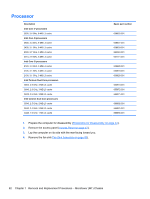
System Board Description System board for use in 3330 models (includes thermal material) Spare part number 663099-001 When replacing the system board, be sure that the following components are removed from the defective system board and installed on the replacement system board: ● Memory modules ● Processor ● Expansion cards To remove the system board: 1. Prepare the computer for disassembly (Preparation for Disassembly on page 42). 2. Remove the access panel (Access Panel on page 43). 3. Lay the computer on its side with the rear facing toward you. 4. Remove the front bezel (Front Bezel on page 45). 5. Remove an expansion cards (Expansion Cards on page 51). 6. Disconnect the power, and data cables from the back of all installed drives. 7. Disconnect all cables from the system board. 8. Remove the six screws that secure the system board to the chassis. 9. Slide the system board toward the front of the chassis, and then lift it up and out of the chassis. To install the system board, reverse the removal procedure. System Board 87
-
 1
1 -
2
-
3
-
4
-
5
-
6
-
7
-
8
-
9
-
10
-
11
-
12
-
13
-
14
-
15
-
16
-
17
-
18
-
19
-
20
-
21
-
22
-
23
-
24
-
25
-
26
-
27
-
28
-
29
-
30
-
31
-
32
-
33
-
34
-
35
-
36
-
37
-
38
-
39
-
40
-
41
-
42
-
43
-
44
-
45
-
46
-
47
-
48
-
49
-
50
-
51
-
52
-
53
-
54
-
55
-
56
-
57
-
58
-
59
-
60
-
61
-
62
-
63
-
64
-
65
-
66
-
67
-
68
-
69
-
70
-
71
-
72
-
73
-
74
-
75
-
76
-
77
-
78
-
79
-
80
-
81
-
82
-
83
-
84
-
85
-
86
-
87
-
88
-
89
-
90
-
91
-
 92
92 -
 93
93 -
 94
94 -
 95
95 -
 96
96 -
 97
97 -
 98
98 -
 99
99 -
 100
100 -
 101
101 -
 102
102 -
103
-
104
-
105
-
106
-
107
-
108
-
109
-
110
-
111
-
112
-
113
-
114
-
115
-
116
-
117
-
118
-
119
-
120
-
121
-
122
-
123
-
124
-
125
-
126
-
127
-
128
-
129
-
130
-
131
-
132
-
133
-
134
-
135
-
136
-
137
-
138
-
139
-
140
-
141
-
142
-
143
-
144
-
145
-
146
-
147
-
148
-
149
-
150
-
151
-
152
-
153
-
154
-
155
-
156
-
157
-
158
-
159
-
160
-
161
-
162
-
163
-
164
-
165
-
166
-
167
-
168
-
169
-
170
-
171
-
172
-
173
-
174
-
175
-
176
-
177
-
178
-
179
-
180
-
181
-
182
-
183
-
184
-
185
-
186
-
187
-
188
-
189
-
190
-
191
-
192
-
193
-
194
-
195
-
196
-
197
-
198
-
199
-
200
-
201
-
202
-
203
-
204
-
205
-
206
-
207
-
208
 |
 |
