HP ProLiant DL388e HP ProLiant DL388e Gen8 Server User Guide - Page 13
DIMM slot locations, System maintenance switch, Description, Switch, Default, Function
 |
View all HP ProLiant DL388e manuals
Add to My Manuals
Save this manual to your list of manuals |
Page 13 highlights
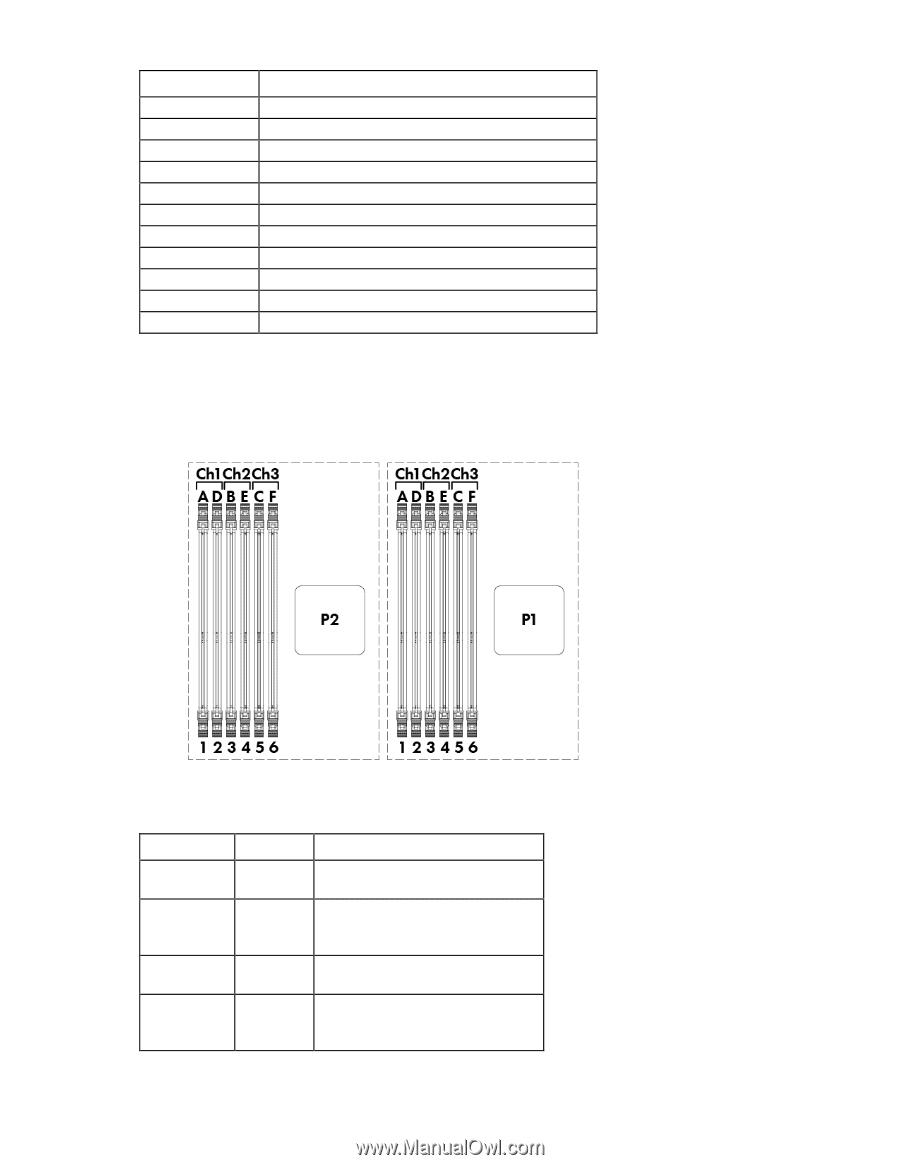
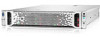
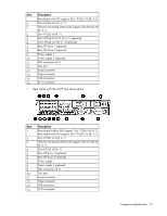
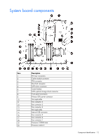
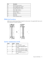
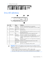
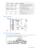
Item 21 22 23 24 25 26 27 28 29 30 31 Description Discovery service connector Drive backplane power connector Drive sideband signal connector Secondary GPU power connector Power supply connector 1 Power supply connector 2 Processor socket 1 Processor 1 DIMM slots SD card slot NMI header System maintenance switch DIMM slot locations DIMM slots are numbered sequentially (1 through 6) for each processor. The supported AMP modes use the letter assignments for population guidelines. System maintenance switch Switch 1 2 5 6 Default Off Off Off Off Function Off = No function On = iLO security is disabled Off = System configuration can be changed On = System configuration is locked Off = Power-on password is enabled On = Power-on password is disabled Off = No function On = ROM reads configuration as invalid Component identification 13
-
 1
1 -
2
-
3
-
4
-
5
-
6
-
7
-
 8
8 -
 9
9 -
 10
10 -
 11
11 -
 12
12 -
 13
13 -
 14
14 -
 15
15 -
 16
16 -
 17
17 -
 18
18 -
19
-
20
-
21
-
22
-
23
-
24
-
25
-
26
-
27
-
28
-
29
-
30
-
31
-
32
-
33
-
34
-
35
-
36
-
37
-
38
-
39
-
40
-
41
-
42
-
43
-
44
-
45
-
46
-
47
-
48
-
49
-
50
-
51
-
52
-
53
-
54
-
55
-
56
-
57
-
58
-
59
-
60
-
61
-
62
-
63
-
64
-
65
-
66
-
67
-
68
-
69
-
70
-
71
-
72
-
73
-
74
-
75
-
76
-
77
-
78
-
79
-
80
-
81
-
82
-
83
-
84
-
85
-
86
-
87
-
88
-
89
-
90
-
91
-
92
-
93
-
94
-
95
-
96
-
97
-
98
-
99
-
100
-
101
-
102
-
103
-
104
-
105
-
106
-
107
-
108
-
109
-
110
-
111
-
112
-
113
-
114
-
115
-
116
-
117
-
118
-
119
-
120
-
121
-
122
-
123
-
124
-
125
-
126
-
127
-
128
-
129
-
130
-
131
-
132
-
133
-
134
-
135
-
136
-
137
-
138
-
139
-
140
 |
 |