HP ProLiant DL388e HP ProLiant DL388e Gen8 Server User Guide - Page 47
Storage controller installation guidelines, Installing a storage controller, CAUTION, IMPORTANT
 |
View all HP ProLiant DL388e manuals
Add to My Manuals
Save this manual to your list of manuals |
Page 47 highlights
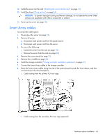
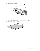
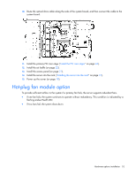
CAUTION: The cache module connector does not use the industry-standard DDR3 mini-DIMM pinout. Do not use the controller with cache modules designed for other controller models, because the controller can malfunction and you can lose data. Also, do not transfer this cache module to an unsupported controller model, because you can lose data. CAUTION: To prevent a server malfunction or damage to the equipment, do not add or remove the capacitor pack while an array capacity expansion, RAID level migration, or stripe size migration is in progress. CAUTION: After the server is powered down, wait for 30 seconds, and then check the amber LED before unplugging the cable from the cache module. If the amber LED flashes after 30 seconds, do not remove the cable from the cache module. The cache module is backing up data. Data will be lost if the cable is detached when the amber LED is still flashing. IMPORTANT: The capacitor pack might have a low charge when installed. If the pack does have low charge a POST error message appears when the server is powered up, indicating that the capacitor pack is temporarily disabled. No action is necessary. The internal circuitry automatically recharges the capacitors and enables the capacitor pack. This process might take up to 4 hours. During this time, the cache module functions properly but without the performance advantage of the capacitor pack. Storage controller installation guidelines • Install the storage controller option in slots 1-3 of the primary PCI riser cage. • Do not install a storage controller option in slot 4 of the primary PCI riser cage. • The secondary PCI riser cage option supports storage controller installation. • For more information on the riser board slot specifications, see "PCIe riser board slot definitions (on page 11)." Installing a storage controller 1. Power down the server (on page 18). 2. Remove all power: a. Disconnect each power cord from the power source. b. Disconnect each power cord from the server. 3. Do one of the following: o Extend the server from the rack (on page 18). o Remove the server from the rack (on page 20). 4. Remove the access panel (on page 21). 5. Install the storage controller ("Expansion board option" on page 70). 6. Connect all necessary internal and external cabling to the storage controller. For more information on these cabling requirements, see the documentation that ships with the option. For more information on internal cable routing in supported drive configurations, see "Storage cabling (on page 82)." 7. Install the access panel (on page 21). Hardware options installation 47
-
 1
1 -
2
-
3
-
4
-
5
-
6
-
7
-
8
-
9
-
10
-
11
-
12
-
13
-
14
-
15
-
16
-
17
-
18
-
19
-
20
-
21
-
22
-
23
-
24
-
25
-
26
-
27
-
28
-
29
-
30
-
31
-
32
-
33
-
34
-
35
-
36
-
37
-
38
-
39
-
40
-
41
-
 42
42 -
 43
43 -
 44
44 -
 45
45 -
 46
46 -
 47
47 -
 48
48 -
 49
49 -
 50
50 -
 51
51 -
 52
52 -
53
-
54
-
55
-
56
-
57
-
58
-
59
-
60
-
61
-
62
-
63
-
64
-
65
-
66
-
67
-
68
-
69
-
70
-
71
-
72
-
73
-
74
-
75
-
76
-
77
-
78
-
79
-
80
-
81
-
82
-
83
-
84
-
85
-
86
-
87
-
88
-
89
-
90
-
91
-
92
-
93
-
94
-
95
-
96
-
97
-
98
-
99
-
100
-
101
-
102
-
103
-
104
-
105
-
106
-
107
-
108
-
109
-
110
-
111
-
112
-
113
-
114
-
115
-
116
-
117
-
118
-
119
-
120
-
121
-
122
-
123
-
124
-
125
-
126
-
127
-
128
-
129
-
130
-
131
-
132
-
133
-
134
-
135
-
136
-
137
-
138
-
139
-
140
 |
 |