HP ProLiant DL388e HP ProLiant DL388e Gen8 Server User Guide - Page 14
NMI header, Drive numbering
 |
View all HP ProLiant DL388e manuals
Add to My Manuals
Save this manual to your list of manuals |
Page 14 highlights
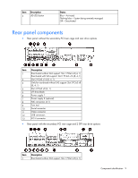
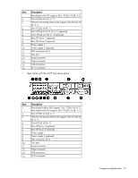
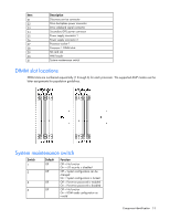
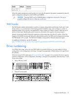
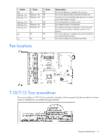
Switch 3, 4, 7, 8, 9, 10, 11, 12 Default - Function Reserved When the system maintenance switch position 6 is set to the On position, the system is prepared to erase all system configuration settings from both CMOS and NVRAM. CAUTION: Clearing CMOS and/or NVRAM deletes configuration information. Be sure to properly configure the server or data loss could occur. NMI header The NMI header enables administrators to perform a memory dump before performing a hard reset. Crash dump analysis is an essential part of eliminating potential reliability issues, such as hangs or crashes in operating systems, device drivers, and applications. Many crashes can freeze a system, requiring you to perform a hard reset. Resetting the system erases any information that supports root cause analysis. Systems running Microsoft® Windows® experience a blue-screen trap when the OS crashes. When this happens, Microsoft® recommends that system administrators perform an NMI event by temporarily shorting the NMI header with a jumper. The NMI event enables a hung system to become responsive again. For additional information, see the HP website (http://h20000.www2.hp.com/bc/docs/support/SupportManual/c00797875/c00797875.pdf). Drive numbering In an 8-bay drive cage, when only one SATA cable is connected, the server can only support a 4-drive configuration. In this configuration, drive bays 1 through 4 are populated, while drive bays 5 through 8 have drive blanks. When the two-port SATA cable option ("Two-port SATA cable" on page 43) is connected, the server supports a 6-drive configuration. In this configuration, drive bays 1 through 6 are populated, while drive bays 7 and 8 have drive blanks. • 8-bay SFF drive model • 8-bay LFF drive model Component identification 14
-
 1
1 -
2
-
3
-
4
-
5
-
6
-
7
-
8
-
 9
9 -
 10
10 -
 11
11 -
 12
12 -
 13
13 -
 14
14 -
 15
15 -
 16
16 -
 17
17 -
 18
18 -
 19
19 -
20
-
21
-
22
-
23
-
24
-
25
-
26
-
27
-
28
-
29
-
30
-
31
-
32
-
33
-
34
-
35
-
36
-
37
-
38
-
39
-
40
-
41
-
42
-
43
-
44
-
45
-
46
-
47
-
48
-
49
-
50
-
51
-
52
-
53
-
54
-
55
-
56
-
57
-
58
-
59
-
60
-
61
-
62
-
63
-
64
-
65
-
66
-
67
-
68
-
69
-
70
-
71
-
72
-
73
-
74
-
75
-
76
-
77
-
78
-
79
-
80
-
81
-
82
-
83
-
84
-
85
-
86
-
87
-
88
-
89
-
90
-
91
-
92
-
93
-
94
-
95
-
96
-
97
-
98
-
99
-
100
-
101
-
102
-
103
-
104
-
105
-
106
-
107
-
108
-
109
-
110
-
111
-
112
-
113
-
114
-
115
-
116
-
117
-
118
-
119
-
120
-
121
-
122
-
123
-
124
-
125
-
126
-
127
-
128
-
129
-
130
-
131
-
132
-
133
-
134
-
135
-
136
-
137
-
138
-
139
-
140
 |
 |