Hitachi P50X901 Owners Guide - Page 23
Connecting A Video And Monaural Audio, Source To Input 1 ~ Front Input
 |
View all Hitachi P50X901 manuals
Add to My Manuals
Save this manual to your list of manuals |
Page 23 highlights
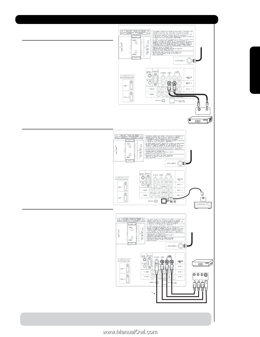
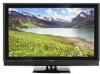
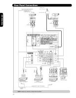
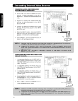
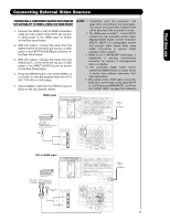
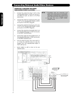
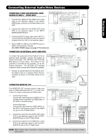
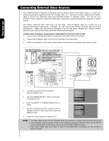
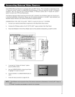
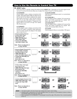
Connecting External Audio/Video Devices First time use CONNECTING A VIDEO AND MONAURAL AUDIO SOURCE TO INPUT 1 ~ FRONT INPUT 1. Connect the cable from the VIDEO OUT of the VCR or the laserdisc player to the INPUT (VIDEO) jack, as shown on the Rear Panel on the right. 2. Connect the cable from the AUDIO OUT of the VCR or the laserdisc player to the INPUT (MONO)/L(AUDIO) jack. 3. Press the INPUTS button, then select INPUT 1 2,3 or Front from the INPUTS menu to view the program from the VCR or the laserdisc player. 4. Select CABLE or AIR from the INPUTS menu to return to the previous channel. (For INPUT FRONT please see page 17 for reference). CONNECTING AN EXTERNAL AUDIO AMPLIFIER To monitor the audio level of the Plasma TV to an external audio amplifier, connect the system as shown on the right. The "OPTICAL OUT" from the Rear Panel is a fixed output. The Volume of the amplifier is controlled by the amplifier, not by the Plasma Television. The OPTICAL OUT terminal outputs all audio sources with Optical IN capability. 1. Connect an optical cable from the Optical out to the Optical input of a separate Stereo System Amplifier as shown on the Rear Panel on the right. CABLE or Air signal Back of VCR VIDEO OUT AUDIO OUT OUTPUT VCR CABLE or Air signal Stereo System Amplifier CONNECTING MONITOR OUT The MONITOR OUT terminal outputs video and audio of CABLE/AIR and INPUTS 1, 2, 3 and Front. It does not output component and HDMI video. 1. Connecting S-Video: Connect the cable from the S-VIDEO OUT of the Rear Panel to the INPUT (S-VIDEO) jack, of the VCR or Laserdisk player. Connecting Video: Connect the cable from the VIDEO INPUT of the VCR or the laserdisc player to the VIDEO out jack on the TV Rear Panel. 2. Connect the cable from the AUDIO IN R of the VCR or the laserdisc player to the OUTPUT (AUDIO/R) jack on the TV Rear Panel. 3. Connect the cable from the AUDIO IN L of the VCR or the laserdisc player to the OUTPUT (AUDIO/L) jack on the TV Rear Panel. OPTICAL IN Stereo System Amplifier or DVD Player CABLE or Air signal Optional VCR or other external components R L V S-VIDEO INPUT NOTE: When making video connections, connect S-Video only or Video only. If both are connected, S-Video takes priority. 23
-
 1
1 -
2
-
3
-
4
-
5
-
6
-
7
-
8
-
9
-
10
-
11
-
12
-
13
-
14
-
15
-
16
-
17
-
 18
18 -
 19
19 -
 20
20 -
 21
21 -
 22
22 -
 23
23 -
 24
24 -
 25
25 -
 26
26 -
 27
27 -
 28
28 -
29
-
30
-
31
-
32
-
33
-
34
-
35
-
36
-
37
-
38
-
39
-
40
-
41
-
42
-
43
-
44
-
45
-
46
-
47
-
48
-
49
-
50
-
51
-
52
-
53
-
54
-
55
-
56
-
57
-
58
-
59
-
60
-
61
-
62
-
63
-
64
-
65
-
66
-
67
-
68
-
69
-
70
-
71
-
72
-
73
-
74
-
75
-
76
-
77
-
78
-
79
-
80
-
81
-
82
-
83
-
84
-
85
-
86
-
87
-
88
-
89
-
90
-
91
-
92
-
93
-
94
-
95
-
96
-
97
-
98
-
99
-
100
-
101
-
102
-
103
-
104
-
105
-
106
-
107
-
108
-
109
-
110
-
111
-
112
-
113
-
114
-
115
-
116
-
117
-
118
-
119
-
120
-
121
-
122
-
123
-
124
-
125
-
126
-
127
-
128
-
129
-
130
-
131
-
132
-
133
-
134
-
135
-
136
-
137
-
138
-
139
-
140
-
141
-
142
-
143
-
144
-
145
-
146
-
147
-
148
-
149
-
150
-
151
-
152
-
153
-
154
-
155
-
156
-
157
-
158
-
159
-
160
-
161
-
162
-
163
-
164
-
165
-
166
-
167
-
168
-
169
-
170
-
171
-
172
-
173
-
174
-
175
-
176
-
177
-
178
-
179
-
180
-
181
-
182
-
183
-
184
-
185
-
186
-
187
-
188
-
189
-
190
-
191
-
192
 |
 |